With scope you will see the pwm signal, with voltmeter you should see a temporary voltage increase
If your friend or you can handle oscilloscope correctly it will be better choice as you will see the signal shape. Multimeter is easier but you see only voltage change when pwm goes through the states
Do you know which trip point is activated when? I have 0 , 1 , 2 , 3 , and 4 So setting the trip point 1 to 32000 didn’t do anything, so I set
echo 32000 > /sys/class/thermal/thermal_zone0/trip_point_4_temp
echo 32000 > /sys/class/thermal/thermal_zone0/trip_point_3_temp
echo 32000 > /sys/class/thermal/thermal_zone0/trip_point_2_temp
echo 32000 > /sys/class/thermal/thermal_zone0/trip_point_1_temp
and now the fan actually spins! YEAH! It is keeping it much cooler, as it was very hot, and hot to touch before. So thank you for pointing me to the trip points but I am not sure what the levels are and how the different trip points affect the fan speed at each point?
1 Like
what 32000 means ? is it the temp in °c * 1000 ? so if i set 40000 the fan will start @40°c
Yes,the temp-value of trippoints is in millicelsius
Mainline has current problems merging dts changes,but i thought daniel has merged my latest version into openwrt where the lowest trippoint is active. I guess you need to update temp from second trip point as only active trips can trigger fan
1 Like
My room is at 22°C, my BPI case is closed, and the temp reported is 46°c. I don’t think that’s really hot… Anyway i tested the commands above @32000 and after that i checked @44000

i think i will set the value to 50000, that’s way enough for me.
tested with official heatsink (with integrated fan), fan runs at level 1 & 2 as it should, so imho current version with fix i’ve sent is correct. also tried using a non-pwm fan (2pin 5v) on the the pwm-pin (+gnd), but this does nothing.
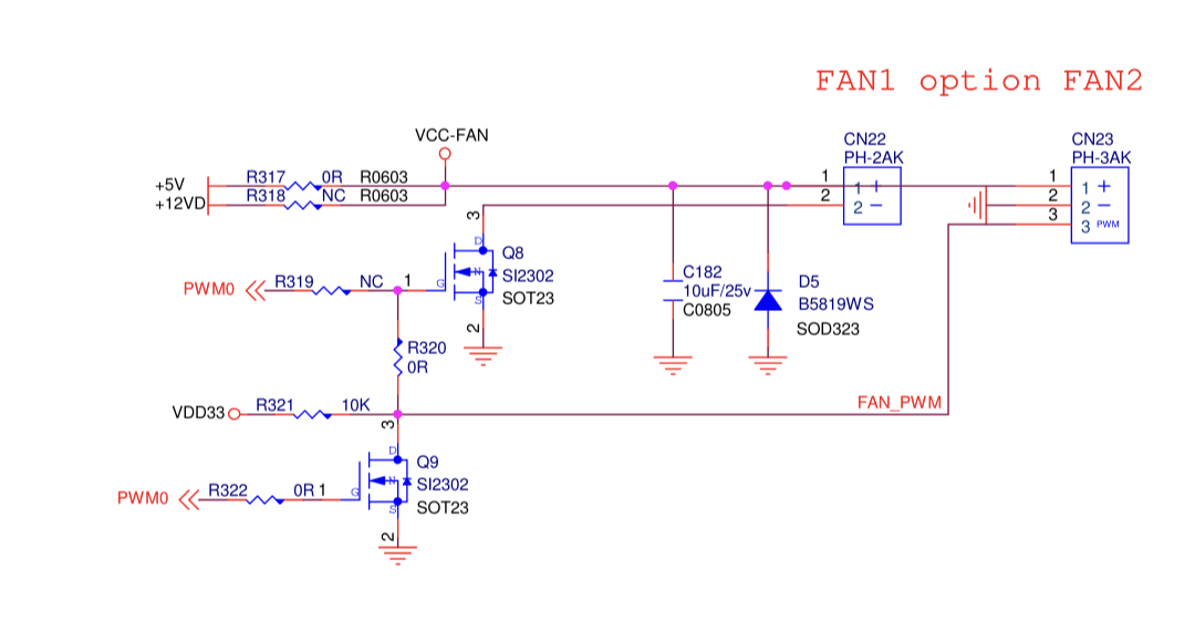
Anyone have any idea on how many volts the 2 PIN fan connector on BPi-R3 should be giving? I was assuming that by default both FAN1 (2pin) and FAN2 (3Pin) ports should be at 5v by default. But a 5v fan does not power up when plugged into FAN1(2Pin) port. It works just fine when using 2 pins of FAN2(3Pin) port. Using a multi-meter I checked both FAN1(2pin) and FAN2(3Pin) and FAN1(2pin) is giving 2.5v instead of 5v. FAN2 (3Pin) is giving 5v as expected. Can anyone else confirm if the FAN1(2Pin) port on their board is giving 2.5v or is there a defect in my board?
Voltage should be on both 5v,but because the pwm-pin is only partly at gnd the measured voltage is lower…,you can measure the voltage with another gnd and then it should be 5v
You are right, FAN1(2PIN) JST Port on the board does show 5v if I do not use the Ground pin of the JST port when testing using a multi-meter.
However, to me that does not make sense, what is the use of this FAN1(2PIN) Port? Since, It can not power a 2Pin-NON-PWM fan, what is the intended use?
Does this mean that FAN1(2PIn)-Jst port also has PWM control capability if ground is used from elsewhere on the board?
Currently, since this port is not able to power the 5v fan being used, I am using 2 pins from FAN2(3PIN) Jst port to power a 2Pin-NON-PWM 5v fan. It would have been nice to be able to use 2Pin port for 2 Pin 5v fan!
Putting the mosfet in the ground connection has 1 advantage.
The pwm pin can be used together with another supply pin, for example 12v.
Thanks for pointing that out. I will just order a 5v, PWM fan and use the FAN2(3Pin) connector. However, I have already butchered the case to fit a 50x50mm fan and I am unable to find a 50x50mm, 5v Pwm fan! I have ordered a 40x40mm, 5v, PWM fan. Now i need to figure out how to cover up the butchered case hole that will be slightly bigger for the new fan. ![]()
So I can safely use ground pin of FAN1(2pin) Jst connector as a PWM signal lead and plug in a 12V-PWM fan into 12v and Grnd elsewhere on the board without having to de-solder and solder R317 and R318?
you could use pwm-pin (gnd) and the 12v pin from the connector near the power jack together…but imho you always need a pwm capable fan…tried with normal 5v fan on 2pin-connector and it does not work. maybe i need to add capacitor in parallel to hold voltage a bit (not bring rectangular signal to the fan)
1 Like
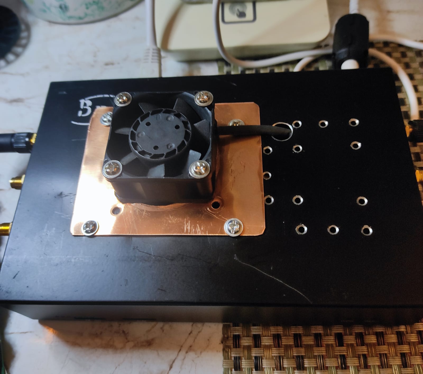
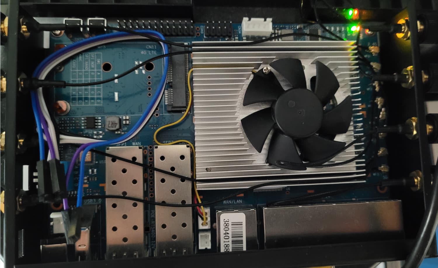
Update: I ordered a 5v PWM fan, modified the case and fan connector, plugged it in and it only spinned for few seconds on boot. Then read through other posts in this thread and figured out the trip points and used echo 45000 > /sys/class/thermal/thermal_zone0/trip_point_3_temp command over SSH. The fan came alive and is working without a glitch, it won’t led the temperature cross 45 degrees Centigrade. Only problem is that this fan is a bit loud. Now I have to search for a quiet 5v (40x40mm) pwm fan. Here is a picture of My BPi-R3 Fan Mod.
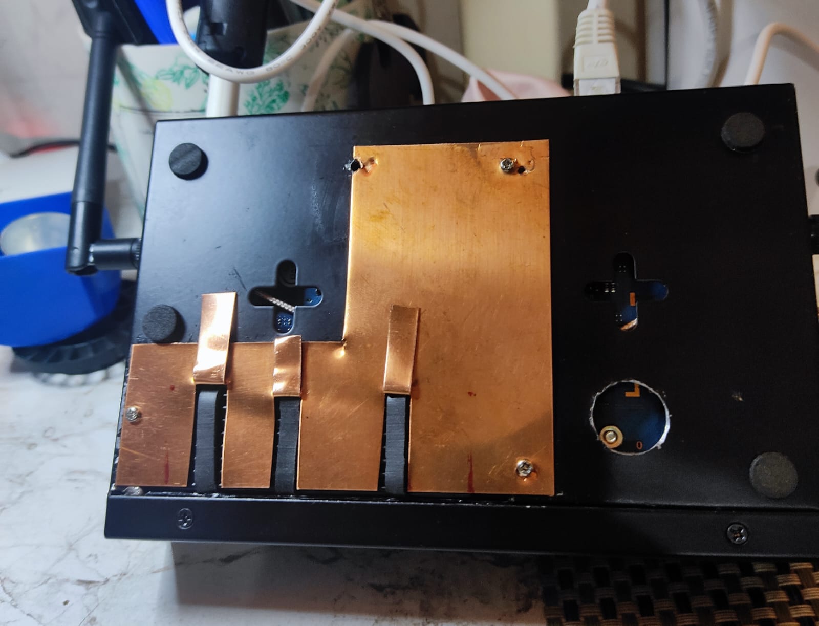
and here is picture of bottom mod, now I can access the SSD, Heat Sink Screws and R317/R318 if I ever wanted to switch Fan voltage from 5v to 12v. Now I am only 3 screws away from changing the SSD and don’t have to worry about removing the antennas and the PCB to to do so.
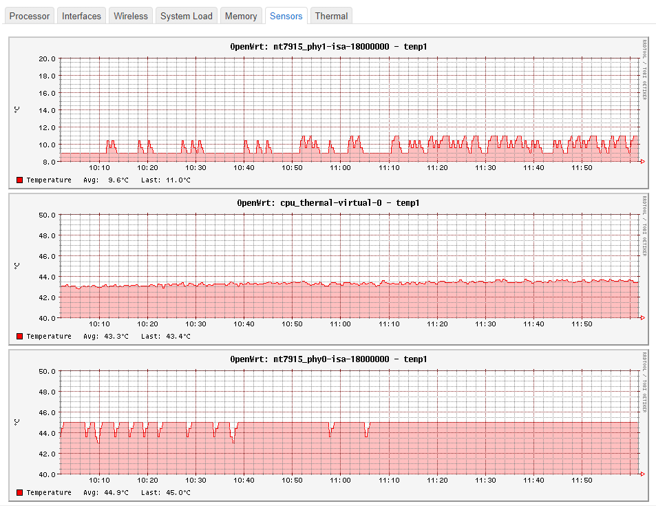
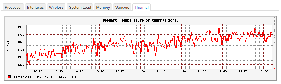
WTF is that ?! I have the official rad/fan, my fan is configured to start @50°c, it never started runing this summer, I’ve never reached this temperature.
This is actualy my temps in a 20°c room.
I’ve never had to make extra holes in my case. In fact, just the radiator is enough, the fan is really if you live in the middle of the Sahara. ![]()
Haha, I am not that good with cutting metal, I badly butchered the case in the process and then had to use .5 mm copper plate to cover up the mess. ![]() For me at room temperature of 25°C my BPi-R3 calls for the fan, all guns blazing, in about 15 minutes and from then on the fan keeps turning on and off in little spurts of few seconds to maintain the temperature of 45°C, the fan gets to pause for longer if I set the trip point at 51°. I am not sure why yours is so cool, mine gets hot rather fast. Thats ok though, since I like my stuff hot
For me at room temperature of 25°C my BPi-R3 calls for the fan, all guns blazing, in about 15 minutes and from then on the fan keeps turning on and off in little spurts of few seconds to maintain the temperature of 45°C, the fan gets to pause for longer if I set the trip point at 51°. I am not sure why yours is so cool, mine gets hot rather fast. Thats ok though, since I like my stuff hot ![]()
did you add a radiator on the chips ?
This is my BPI-R3
in my case just the radiator would be enough, as the fan never start…
yup, 60 x 60 x 10mm Black Anodised Aluminum Heatsink Cooler Radiator, that covers the main chips except for WiFi chips which have smaller Raspberry pi radiators of their own. eMMc chip is partially covered by the 60mm sink.