Hello guys, today, I will show you my last work. I integrate the Banana Pi M5 and Raspberry Pi 4 with my Cyclone IV FPGA dev kit board through USB<->RS232 conversor. The SBC send to the FPGA the last CPU temperature.
The FPGA is amazing, with these I can create infinite possibilities of logical combination circuits, they are much faster than microcontrollers. This is possible because the FPGA “builds” physical logical combination circuits inside the IC, but I can “rebuild” when I must to do this (Field Programmable Gate Array).
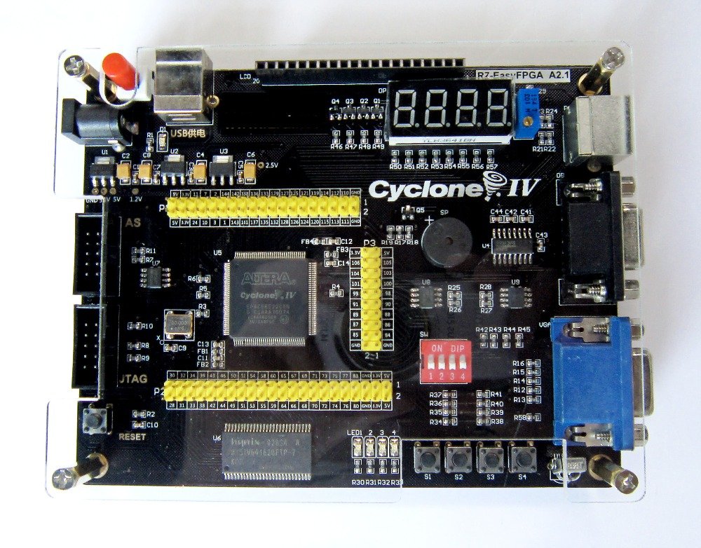
In this case, this is the beginning to integrate another functions. For this little project, I send the information through CH340 (USB<->RS232 converter) to the FPGA. I need to program the UART inside of the FPGA to receive the information correctly. My dev kit board has one MAX232 (RS232 <-> TTL conversor) , the MAX232 has a standard specified maximum open-circuit voltage of 25 volts and will convert to TTL (0 to 5V).

In the VHDL language, you must have caution because the logic is executed paralleling and not sequencialling, this can be confusing when you write the hardware description. But, this can help in specific situations, for example, you can segment the logic in the several components without worrying about blocking another part of the logic. In my project, I create 2 components, one UART component (to receive and send the information of the SBC) and a BCD to 7 segment decoder (similar to 7447 IC). With this practice, you can describe your hardware with more nimbly.
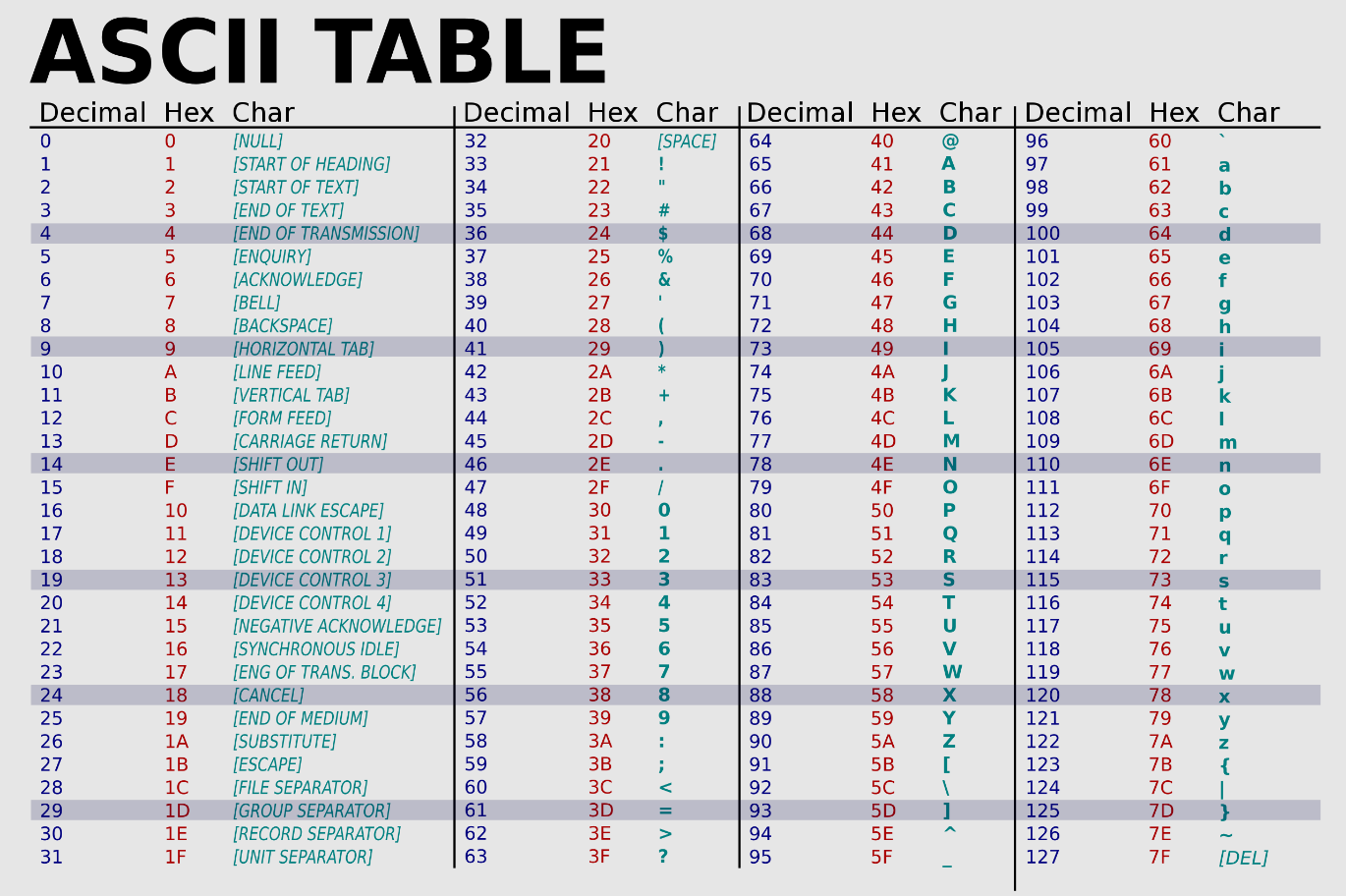
In the “toplevel” program I create a state of machine to read the UART buffer and wait for the start byte (I choose the “0x61, ‘a’ character in the ASCII table).
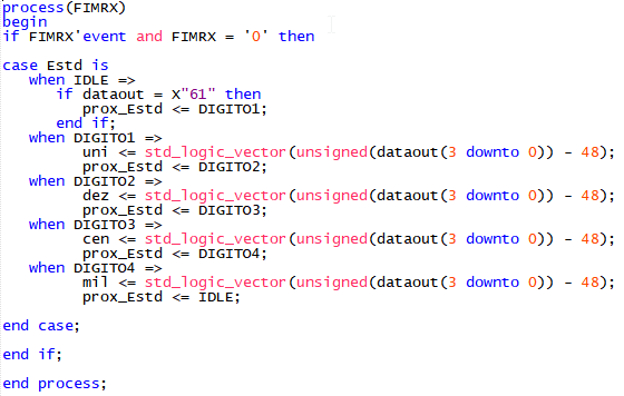
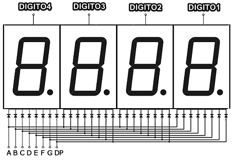
The signal FIMRX is the flag to signal the new information in the UART buffer (dataout). When the FIMRX falling edge the state of machine will verifier if the UART buffer dataout = X”61, if true the state machine will go to the next state. The next state (DIGITO1) is the last significant number (hundredth), the next state (DIGITO2) is the tenth number, the next state (DIGITO3) is the unit and the last state (DIGITO4) is the ten number. In this case, the state of machine needs to receive 5 bytes to complete all the states so the numbers are refreshed. The signal uni, dez, cen, mil is related with the 7 segments display, each signal is the one different display.
In the display component, I need to create a logic to multiplex four 7 segment displays, each display has to be turned on for 1 ms and the FPGA must have turned on the necessary segments.
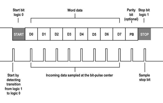
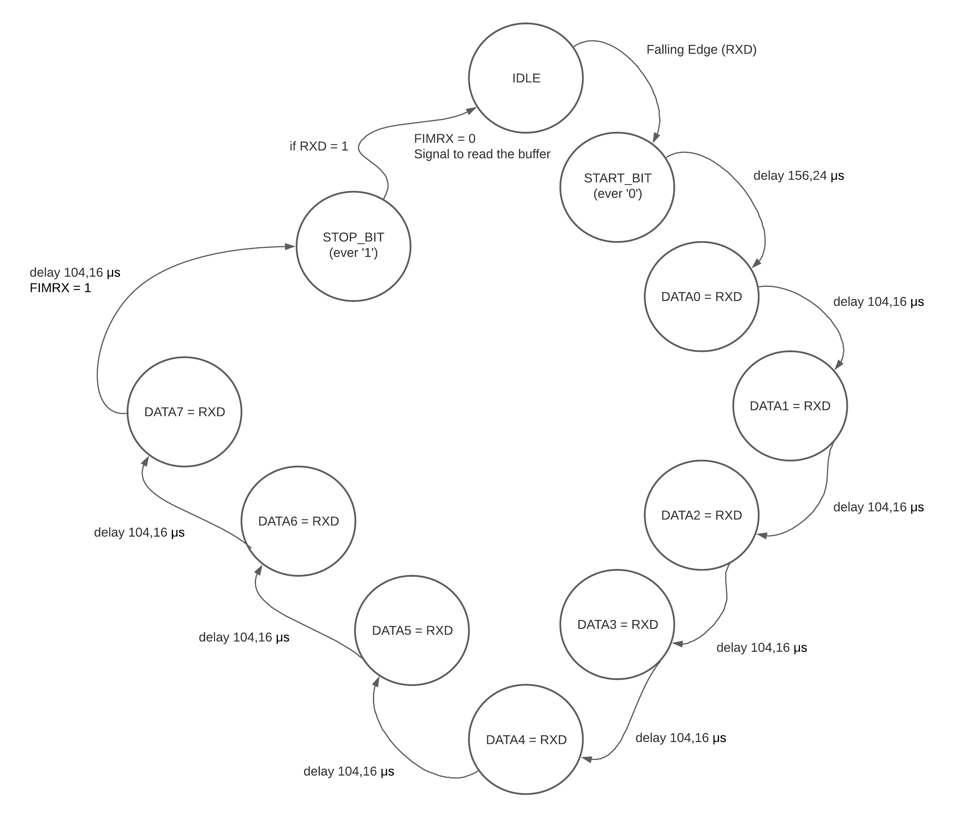
Lastly, the UART component. Inside this component there is another state of machine. The uart protocol should work as follows:
process(clk) variable prescaler : integer range 0 to 7812; begin
if clk’event and clk = ‘1’ then
CASE EstdRX is when IDLE => FIMRX <= ‘0’; if RXD = ‘0’ then prox_EstdRX <= START_BIT; end if;
when START_BIT =>
		if prescaler < 7812 then
			prescaler := prescaler + 1;
		else
			prescaler := 0;
			dataout_buffer <= "00000000";
			prox_EstdRX <= DATA0;
			dataout_buffer(0) <= RXD;
		end if;

when DATA0 =>
		if prescaler < 5208 then
			prescaler := prescaler + 1;
		else
			prescaler := 0;
			prox_EstdRX <= DATA1;
			dataout_buffer(1) <= RXD;
		end if;

when DATA1 =>
		if prescaler < 5208 then
			prescaler := prescaler + 1;
		else
			prescaler := 0;
			prox_EstdRX <= DATA2;
			dataout_buffer(2) <= RXD;
		end if;

when DATA2 =>
		if prescaler < 5208 then
			prescaler := prescaler + 1;
		else
			prescaler := 0;

			prox_EstdRX <= DATA3;
			dataout_buffer(3) <= RXD;
		end if;

when DATA3 =>

		if prescaler < 5208 then
			prescaler := prescaler + 1;
		else
			prescaler := 0;

			prox_EstdRX <= DATA4;
			dataout_buffer(4) <= RXD;
		end if;

when DATA4 =>

		if prescaler < 5208 then
			prescaler := prescaler + 1;
		else
			prescaler := 0;

			prox_EstdRX <= DATA5;
			dataout_buffer(5) <= RXD;
		end if;

when DATA5 =>

		if prescaler < 5208 then
			prescaler := prescaler + 1;
		else
			prescaler := 0;
			prox_EstdRX <= DATA6;
			dataout_buffer(6) <= RXD;
		end if;

when DATA6 =>

		if prescaler < 5208 then
			prescaler := prescaler + 1;
		else
			prescaler := 0;
			prox_EstdRX <= DATA7;
			dataout_buffer(7) <= RXD;
		end if;

when DATA7 =>
		if prescaler < 5208 then
			prescaler := prescaler + 1;
		else
			prescaler := 0;
			prox_EstdRX <= STOP_BIT;
		end if;

when STOP_BIT =>
		FIMRX <= '1';
		if RXD = '1' then
			if prescaler < 5208 then
				prescaler := prescaler + 1;
			else
				prescaler := 0;
				prox_EstdRX <= IDLE;
				dataout <= dataout_buffer;
			end if;
		end if;
end case;
end if; end process;
In this case, the first state waits for the falling edge in RXD (Start bit, necessarily bit 0), when the falling edge is detected the state of machine generate a delay of 104,16μs + 52,08μs. This time is based on the baud rate, in this case, I use 9600bps, in this baud rate the bit has 1/9600bps = 104,16μs/bit in the data bus. This task is similar to the UART in the microcontrollers and other electronics devices. You can use a microcontroller to do this too! (microcontrollers are cheaper than FPGAs).
Done! This state of machine will receive each byte and signalize to the top level, the top level is responsible to connect all the components.