Could someone who already has the board or has the 3D CAD files share the sizes of the chips that need heatsinks?
I wanted to order some aluminum heatsinks from aliexpress with the board but couldn’t find the size of the chips. The DXF files only have the pin layout, but not the size of the actual chips.
The chips in question are:
CPU / SoC: 22mm x 22mm
eMMC: 11,5mm x 13mm
DDR4 (2x): 10mm x 15mm
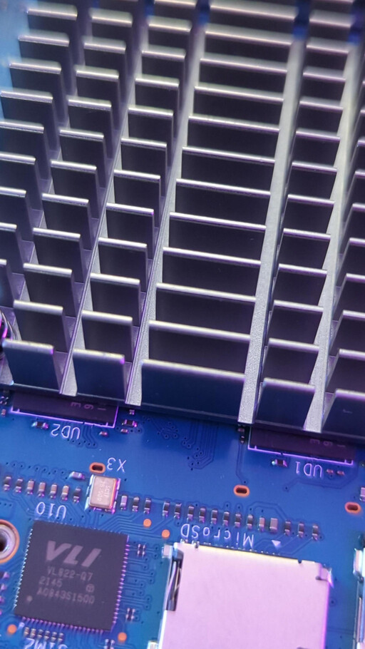
USB Host (next to the micro-SD slot): 9mm x 9mm
SFP cage: ~40mm x 14mm (beware though, from what I have read so far, the cage has ventilation holes and the heatsink would rather block them and cool the cage instead. So, a fan might be the better solution here)
Did I miss anything?
Of course, I’d rather use the official heatsink, but this isn’t available yet.
Edit 1: Added chip measurements from online specs and guessing from board photo in Wiki.
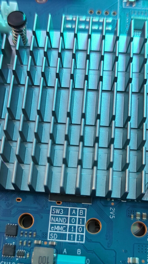
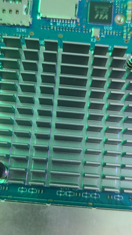
i measured for SoC 20.7x20.7 as outer dimensions and 15.2x15.2 as inner one (as mt7988 SoC is not plane), DDR (UD1,UD2): 10.2x13.2
maybe adding heatsinks for chips on the WIFI-NIC…but i currently cannot access them on my board as it is mounted in the middle of my boards combined using spacers
You are probably just one of five people who have the WIFI NIC yet. And since the board is going to change, the required heatsinks will probably change anyway.
And from the pictures in the Wiki it looks like the NIC has standard mounting holes similar to the main board. Also 39mm distance?
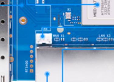
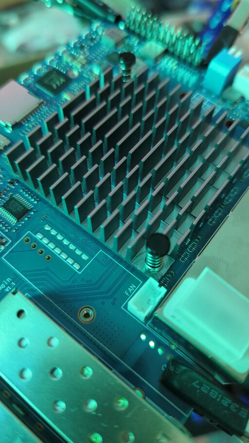
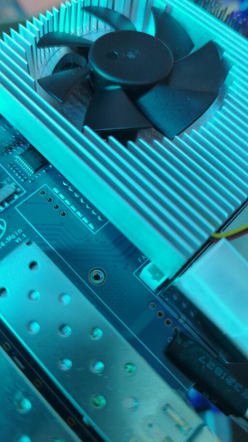
The heatsink design above doesn’t accommodate the PH-3PIN Connector - compared with the BPI-R3, the fan header was moved, seemingly to make space for the (optional) POE Module RT5400. The heatsink render above omits the fan header, and would collide with it without adjustments being made to the design.
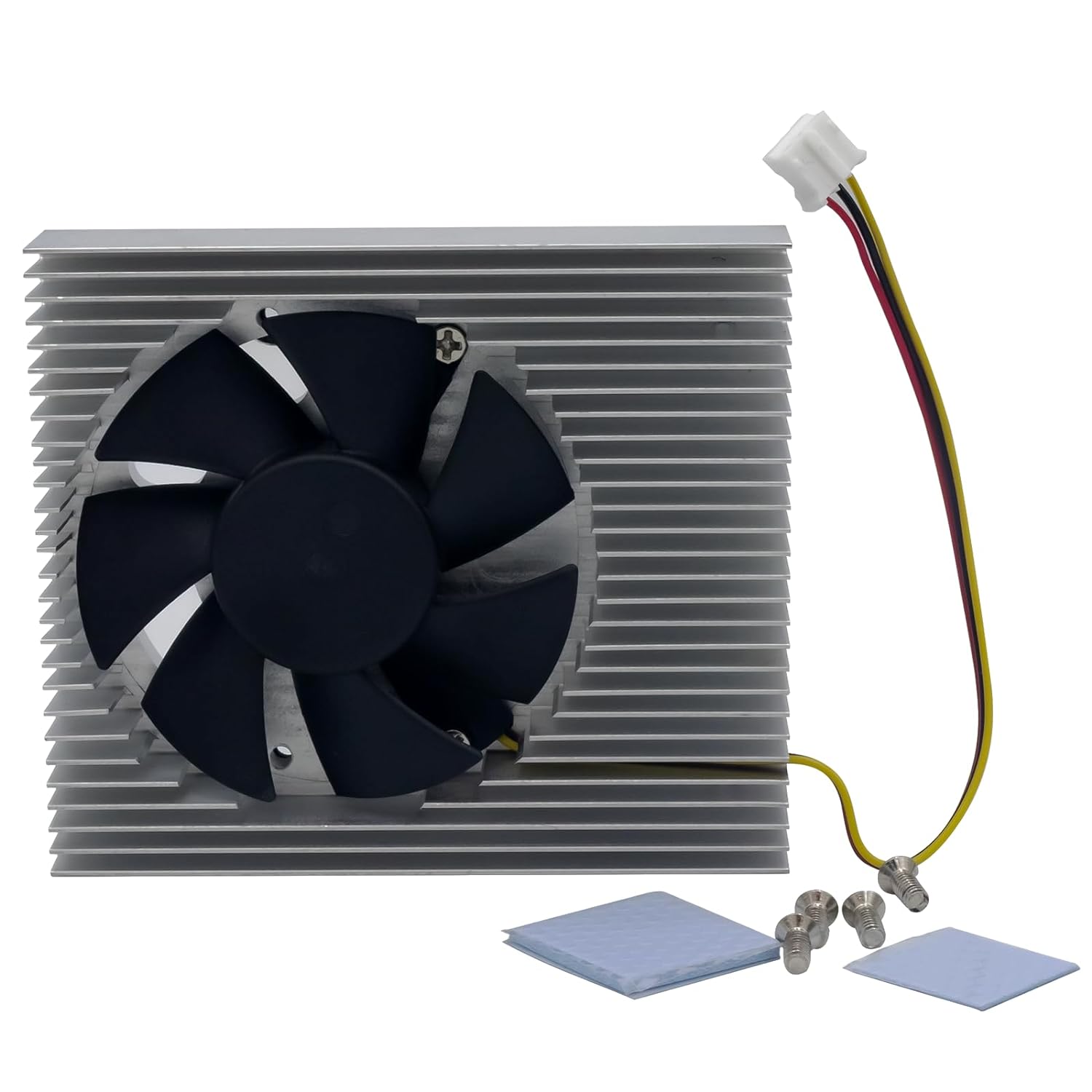
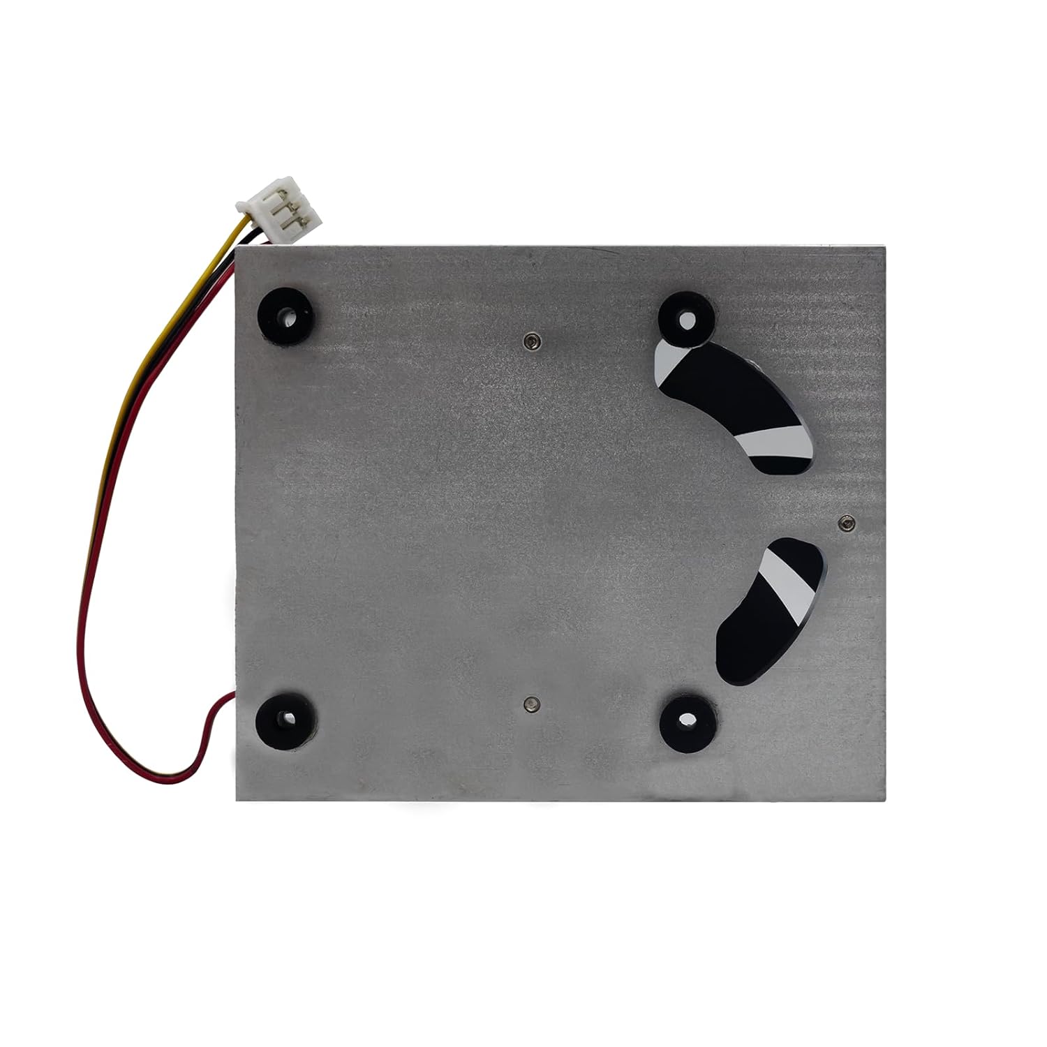
A little annoying, as the existing fan/radiator products (pictured) from the R3 would work on the R4 (albeit rotated, compared with how they are intended to be mounted), but will need to be altered in order to to make way for the change in fan header placement.
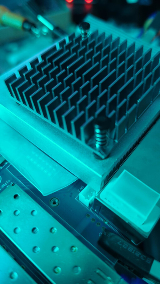
To illustrate the disparity in offset, passive heatsink designs for the R3 fit without issue; anything with more than ~2mm overlap outside the mounting point will collide with the fan header:
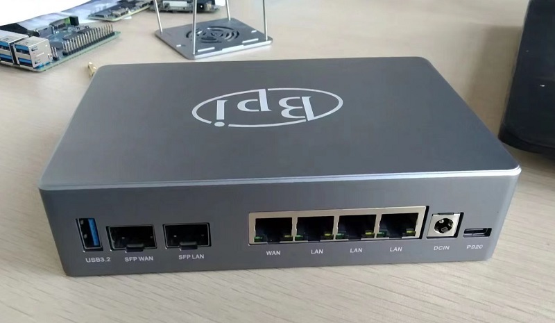
I would also appreciate the 3d model for this case design being made available, as I have not been able to find a retail product, and will need to design one from scratch and print it myself; unless, perhaps someone else has had more luck than I in finding a manufacturer who is selling cases for the BPI-R4?
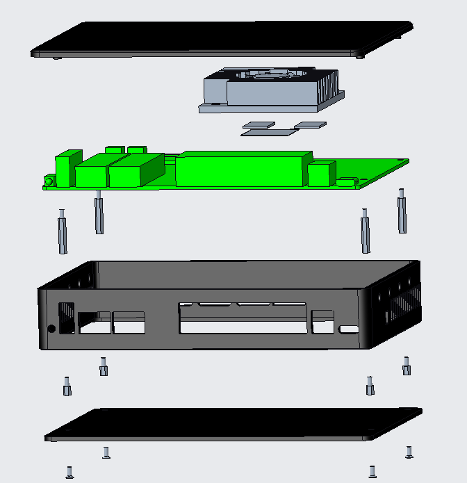
The first image you show, what are the dimensions of that heatsink? And does it fully cover the DDR and eMMC chips as well or just partially like seen in earlier images from Frank?
Nah, unfortunately @sinovoip did not release the CAD / 3D model of the green board shown in your image yet or ever. I think I read they do not publish those, which would be a pity.
The only data released is the PCB schematic as DXF file, but this is only 2D, so rather useless for designing heatsinks or cases.
I don’t know if there is any software that could generate a 3D model from multiple photographs taken from the board. Maybe there is, then that could be the base for further work.
Edit: There is, and it is called Meshroom. Needs dozens of images from different angles around the object and is then able to compute a 3D mesh. Not sure if those can be used in CAD applications though. So yeah, if someone has the board and a good camera plus tripod, take some hundred pictures all around the board and let’s go.
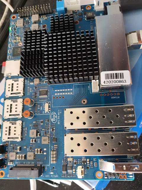
50mm x 50mm, and ~2mm of the ram/emmc aren’t covered, which are accounted for via a thermal pad
unfortunately, there is 0mm of space between the heatsink and fan header, so in order to align with the mounting holes + fully cover ram/emmc it would need to be an asymmetrical shape
I have a decent camera, and a tripod, but no automated means of rotating the device itself at the moment - when I have a moment I will check out meshroom, as it could be quite generally helpful if I can use it to generate models that could be sliced for my printer; thanks for the share
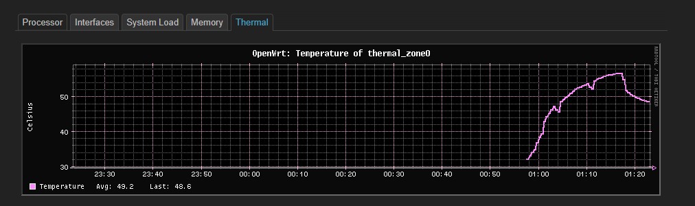
This is the result of stressing all cores with these heatsinks. I’m using Daniel’s repo. I also ported LVTS driver to 6.1 kernel for the thermal sensors to work