I was considering doing that after buying a 2.5 GbE version, but I ended up getting another 2xSFP+ and can no longer verify the dimensions of the back panel for tight fit. If you have one on hand, you can actually help with that by measuring the width of the 2.5 GbE connector housing and the height (from the PCB or together with the PCB) as accurately as possible with calipers. The official DXF is of little help here, as the manufacturer can change parts suppliers freely.
If you can, and doing custom case, you can and make special pockets in side walls, avoid antena cables going across the PCB, route those straight over the edge and then to the connector.
This is a neat idea. But in this case, the pigtails absolutely have to be facing away from the Mini PCIe connectors to avoid picking up RF noise from the main PCB.
1 Like
Cool design!
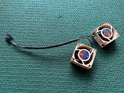
I’ll attempt the project very soon, just one clarification. You mention to source “2 × Noctua NF-A4x20 5V PWM”, but these are 4-pin fans, and in the guide you only say to plug 3 “The fans can be connected in parallel to the GPIO header instead; pin 4 is 5V, pin 6 is GND, and PIN 7 is PWM;”.
Are you using an adapter from 4 to 3 pins?
The extra pin of each fan is a tachometer output. You can leave those disconnected or connect them to the unused GPIO pins for RPM monitoring (check out this tool). For my build I just cut off the fan connectors, soldered on extension wires and crimped female Dupont connectors onto the ends. I also reused the sleeve that came from the factory and secured it with heat-shrink to make the harness look tidier.
1 Like
I appreciate your answer. I was able to make it work perfectly. I have a few more questions:
- Use this script for OpenWrt which reads all temperature sensors in hwmon and adjusts the fan speed according to the highest reading; you can dial in your own temp thresholds there
- Put the script into /opt (or any persistent directory) with the following command (if using Linux or macOS): scp -O /…/fan_pwm.sh [email protected]:/opt/
- Make it executable: chmod +x fan_pwm.sh
- Make it run at startup: sed -i ‘/^exit/i /opt/fan_pwm.sh &\n’ /etc/rc.local
For a common mortal that is approaching this from a 0-knowledge perspective, how do I do this exactly? I was capable of making the script run from ssh, but I don’t know how to save that and make it run on startup.
- Rather than making the grounding strips by hand, order them to be laser-cut instead—it’s likely to cost less than your time spent measuring, drilling and cutting
Are there any CONS in not using the grounding strip? I installed everything without it, and it’s working decent.
Oh, BTW, just for laughing a bit, instead of soldering the EMI shielding, I used superglue ![]()
![]()
Regardless, before I was somewhere at 78/79 noise, now I sit at around 85. It’s still progress!
For a common mortal that is approaching this from a 0-knowledge perspective, how do I do this exactly? I was capable of making the script run from ssh, but I don’t know how to save that and make it run on startup.
If you’re creating the script on the system rather than transferring over:
- Install a text editor with
apk add nanooripkg install nanodepending on your OpenWrt release, if not already installed - Run
nano /opt/fan_pwm.sh - Copy/paste the script code into the editor; make changes to the temperature threshold values if desired
- Press Ctrl+X, then Y to save
- Run
chmod +x /opt/fan_pwm.shto make the script executable - Run
sed -i ‘/^exit/i /opt/fan_pwm.sh &\n’ /etc/rc.localto make it run on startup - Verify by running
cat /etc/rc.local; you should see the line/opt/fan_pwm.sh & - Run
/opt/fan_pwm.sh &to launch the script without rebooting; you should hear the fans slow down - For further tweaking of the temperature thresholds, go back to steps 2 and 4
- Install the
luci-app-statisticsandlm-sensorspackages to track the temperature
Are there any CONS in not using the grounding strip? I installed everything without it, and it’s working decent.
In my experience, the improvement from the grounding strips and EMI shielding together was marginal, but that could change depending on how congested your Wi-Fi environment is. I also hope the BE19 will be inherently less susceptible to noise to benefit from extra grounding.
Changes in v1.1
- Added back plates for the 2.5GbE version. Can’t test for fit, as I don’t have a 2.5GbE version to verify dimensions. Adjust the STEP file if necessary. There’s also not enough room to use the PoE module and TTL to USB adapter in the same device and I gave up on finding alternative placement for the adapter.
- Corrected an error which made one of the baked-in support fins on the back plate disconnect from the model after slicing.
- Revised and expanded documentation.
1 Like
Quick question how much difference did it make for noise, and how do you cool the WiFi card now?
Looking at my previous experiments, when everything else has been sorted out (SFP cages populated, pigtails routed properly), not using the stock metal case can lower the noise by about ~9 dBm.
I have a copper heatsink mounted on top of custom-made EMI shielding. Thermal pads under the shield can, thermal adhesive tape between the heatsink and the shield can.

2 Likes
Hmm, I was looking for a less custom and cheaper solution lol
Slapping three smaller heatsinks on the ICs with thermal tape will do just as well. One large heatsink won’t work, though, as the ICs differ in height.
Ah ok, cool thanks for that info
I’ll probably adapt the top plate to support 1 90mm fan instead since I already have a 90mm fan installed
@Betonmischer Man, you’re out-of-mind! (in a very very good way!) ![]()
If I can find all the pieces, I’ll give it a try with ABS (any clue for support material?).
Fans should be pushing or pulling air?
Out of my curiosity, what CAD did you use to design this beauty?
1 Like
Thank you!
A guy on MakerWorld had success with ABS, but he didn’t post any photos and I’d be worried about ABS warping with such large flat parts. If you’re willing to give it a try, though, I’d pick the ABS-compatible support material from the same manufacturer as the ABS. A way better option dimentional stability-wise would be GF or CF-reinforced ABS/ASA, but those might require a larger than 0.4mm nozzle. BTW, at first I was apprehensive of PLA due to the low glass transition temperature of 55–65 °C, but the R4 should never get the air inside the case anywhere close to that.
As for the fans, they fit both ways, but I’d install them for intake so that the cold air hits the Wi-Fi board and the SFP cages first.
I used Fusion 360. Or rather, used this project to learn Fusion, which lead to a file with a pretty messy history, otherwise I’d share it and made the project fully open-source. ![]()
Changes in v1.2.0
- Added part variants for a 5x3 antenna arrangement in anticipation of the upcoming BE19 NIC, now up to 16 antennas total are supported.
- Added printable washers for SMA connectors.
- Restored supports for the back plates, some of which were missing in v1.1.0.
Would anyone want an add-on for mounting the case in a 10-inch rack?
2 Likes
…would you be interested in adapting that model for the BPI R4 Pro out of the specs?
Yes. It would help if Sinovoip published DXF drawings of the board, which they haven’t yet. So I’m waiting until the Pro is available to buy, which I’d have to do regardless to verify the dimensions.
I oredered the board in the ongoing presale.
When I’ll get it, if there’s nothing better, I’ll be happy to send you measures.