Hello!
Here is the boot-log:
[USBD] USB PRB0 LineState: 0
[USBD] USB cable/ No Cable inserted!
[PLFM] Keep stay in USB Mode
Platform initialization is ok
wait for frequency meter finish, CLK26CALI = 0x81
mt_pll_post_init: mt_get_cpu_freq = 1040000Khz
wait for frequency meter finish, CLK26CALI = 0x90
mt_pll_post_init: mt_get_bus_freq = 273000Khz
wait for frequency meter finish, CLK26CALI = 0x81
mt_pll_post_init: mt_get_mem_freq = 133250Khz
[PWRAP] pwrap_init_preloader
[PWRAP] pwrap_init
[PWRAP] _pwrap_init_sistrobe [Read Test] fail,index=0,rdata=2D52
[PWRAP] _pwrap_init_sistrobe [Read Test] fail,index=1,rdata=2D52
[PWRAP] _pwrap_init_sistrobe [Read Test] fail,index=2,rdata=800
[PWRAP] _pwrap_init_sistrobe [Read Test] pass,index=3 rdata=5AA5
[PWRAP] _pwrap_init_sistrobe [Read Test] pass,index=4 rdata=5AA5
[PWRAP] _pwrap_init_sistrobe [Read Test] pass,index=5 rdata=5AA5
[PWRAP] _pwrap_init_sistrobe [Read Test] pass,index=6 rdata=5AA5
[PWRAP] _pwrap_init_sistrobe [Read Test] pass,index=7 rdata=5AA5
[PWRAP] _pwrap_init_sistrobe [Read Test] pass,index=8 rdata=5AA5
[PWRAP] _pwrap_init_sistrobe [Read Test] pass,index=9 rdata=5AA5
[PWRAP] _pwrap_init_sistrobe [Read Test] fail,index=10,rdata=1001
[PWRAP] _pwrap_init_sistrobe [Read Test] fail,index=11,rdata=B54B
[PWRAP] _pwrap_init_sistrobe [Read Test] fail,index=12,rdata=B54B
[PWRAP] _pwrap_init_sistrobe [Read Test] fail,index=13,rdata=B54B
[PWRAP] _pwrap_init_sistrobe [Read Test] fail,index=14,rdata=B54B
[PWRAP] _pwrap_init_sistrobe [Read Test] fail,index=15,rdata=B54B
[PWRAP] _pwrap_init_sistrobe [Read Test] fail,index=16,rdata=B54B
[PWRAP] _pwrap_init_sistrobe [Read Test] fail,index=17,rdata=B54B
[PWRAP] _pwrap_init_sistrobe [Read Test] fail,index=18,rdata=2003
[PWRAP] _pwrap_init_sistrobe [Read Test] fail,index=19,rdata=6A97
[PWRAP] _pwrap_init_sistrobe [Read Test] fail,index=20,rdata=6A97
[PWRAP] _pwrap_init_sistrobe [Read Test] fail,index=21,rdata=6A97
[PWRAP] _pwrap_init_sistrobe [Read Test] fail,index=22,rdata=6A97
[PWRAP] _pwrap_init_sistrobe [Read Test] fail,index=23,rdata=6A97
[PWRAP] _pwrap_init_reg_clock
[PMIC_WRAP]wrap_init pass,the return value=0.
[pmic6323_init] Preloader Start..................
[pmic6323_init] PMIC CHIP Code = 0x2023
INT_MISC_CON: 0 TOP_RST_MISC: 0
pl pmic powerkey Press
[pmic6323_init] powerKey = 1
[pmic6323_init] is USB in = 0xB004
[pmic6323_init] Reg[0x11A]=0x1B
pmic setup LED
[pmic6323_init] Done...................
mt7623 disable long press reset ->>>>>
mt7623 disable long press reset <<<<<-
mt7623 VPA supplied by 1.0V to MT7530 ->
mt7623 VPA supplied by 1.0V to MT7530 <-
mt7623 enables RG_VGP1_EN for LCM ->
mt7623 enables RG_VGP1_EN for LCM <-
MT7623 E2 setting =>
MT7623 E2 setting <=
[PLFM] Init I2C: OK(0)
[PLFM] Init PWRAP: OK(0)
[PLFM] Init PMIC: OK(0)
[PLFM] chip[CA00]
[BLDR] [Support SD/eMMC] Build Time: 20170905-112929
==== Dump RGU Reg ========
RGU MODE: 4D
RGU LENGTH: FFE0
RGU STA: 0
RGU INTERVAL: FFF
RGU SWSYSRST: 0
==== Dump RGU Reg End ====
RGU: g_rgu_satus:0
mtk_wdt_mode_config mode value=10, tmp:22000010
PL P ON
WDT does not trigger reboot
RGU mtk_wdt_init:MTK_WDT_DEBUG_CTL(590200F3)
kpd read addr: 0x0040: data:0x4001
Enter mtk_kpd_gpio_set!
kpd debug column : 0, 0, 0, 0, 0, 0, 0, 0
kpd debug row : 0, 0, 0, 0, 0, 0, 0, 0
after set KP enable: KP_SEL = 0x0 !
MTK_PMIC_RST_KEY is used for this project!
[RTC] get_frequency_meter: input=0x0, ouput=5
[RTC] get_frequency_meter: input=0x0, ouput=3967
[RTC] get_frequency_meter: input=0x0, ouput=5
[RTC] get_frequency_meter: input=0x0, ouput=0
[RTC] get_frequency_meter: input=0x0, ouput=0
[RTC] bbpu = 0x6, con = 0xB9BA
rtc_first_boot_init
[RTC] get_frequency_meter: input=0x0, ouput=5
[RTC] get_frequency_meter: input=0x0, ouput=3967
[RTC] get_frequency_meter: input=0x0, ouput=5
[RTC] get_frequency_meter: input=0x0, ouput=0
[RTC] get_frequency_meter: input=0x0, ouput=0
rtc_2sec_stat_clear
rtc_2sec_reboot_check cali=1280
rtc_2sec_stat_clear
[RTC] irqsta = 0x0, pdn1 = 0x0, pdn2 = 0x201, spar0 = 0xC0, spar1 = 0x800
[RTC] new_spare0 = 0x0, new_spare1 = 0x1, new_spare2 = 0x1, new_spare3 = 0x1
[RTC] bbpu = 0x6, con = 0x426, cali = 0x500
pl pmic powerkey Release
[PLFM] Power key boot!
[RTC] rtc_bbpu_power_on done
[EMI] mcp_dram_num:0,discrete_dram_num:1,enable_combo_dis:0
[EMI] PCDDR3
[Check]mt_get_mdl_number 0x0
[EMI] eMMC/NAND ID = 0,0,0,0,0,0,0,0,0,0,0,0,0,0,0,0
[EMI] MDL number = 0
[EMI] emi_set eMMC/NAND ID = 0,0,0,0,0,0,0,0,0,0,0,0,0,0,0,0
[EMI][Vcore]0x21E=0x48,0x220=0x48
[EMI][Vmem]0x554=0x0
wait for frequency meter finish, CLK26CALI = 0x81
[EMI] PCDDR3 DRAM Clock = 1599912 KHz, MEMPLL MODE = 2
[EMI] PCDDR3 RXTDN Calibration:
Start REXTDN SW calibration...
drvp=0xB,drvn=0x8
[EMI] pinmux = 4
===============================================================================
dramc_write_leveling_swcal
===============================================================================
delay byte0 byte1 byte2 byte3
-----------------------------
0 0 0 0 0
1 0 0 0 1
2 0 0 0 1
3 0 1 0 1
4 0 1 1 1
5 0 1 1 1
6 0 1 1 1
7 0 1 1 1
8 0 1 1 1
9 0 1 1 1
10 1 1 1 1
11 1 1 1 1
12 1 1 1 1
13 1 1 1 1
14 1 1 1 1
15 1 1 1 1
pass bytecount = 4
byte_i status best delay
0 2 10
1 2 3
2 2 4
3 2 1
========================================
[write leveling]DQS: 0x143A, DQM: 0x143A
[write leveling after remap]DQ byte0 reg: 0x200 val: 0xAAAA3333
[write leveling after remap]DQ byte1 reg: 0x204 val: 0x3333AAAA
[write leveling after remap]DQ byte2 reg: 0x208 val: 0x44441111
[write leveling after remap]DQ byte3 reg: 0x20C val: 0x11114444
=============================================
X-axis: DQS Gating Window Delay (Fine Scale)
Y-axis: DQS Gating Window Delay (Coarse Scale)
=============================================
0 8 16 24 32 40 48 56 64 72 80 88 96 104 112 120
--------------------------------------------------------------------------------
0000:| 0 0 0 0 0 0 0 0 0 0 0 0 0 0 0 0
0001:| 0 0 0 0 0 0 0 0 0 0 0 0 0 0 0 0
0002:| 0 0 0 0 0 0 0 0 0 0 0 0 0 0 0 0
0003:| 0 0 0 0 0 0 0 0 0 0 0 0 0 0 0 0
0004:| 0 0 0 0 0 0 0 0 0 0 0 0 0 0 0 0
0005:| 0 0 0 0 0 0 0 0 0 0 0 0 0 0 0 0
0006:| 0 0 0 0 0 0 0 0 0 0 0 0 0 0 0 0
0007:| 0 0 0 0 0 0 0 0 0 0 0 0 0 0 0 0
0008:| 0 0 0 0 0 0 0 0 0 0 0 0 0 0 0 0
0009:| 0 0 0 0 0 0 0 0 0 0 0 0 0 0 0 0
000A:| 0 0 0 0 0 0 0 0 0 0 0 0 0 0 0 0
000B:| 0 0 0 0 0 0 0 0 0 0 0 0 0 0 0 0
000C:| 0 0 0 0 0 0 0 0 0 0 0 0 0 0 0 0
000D:| 0 0 0 0 0 0 0 0 0 0 0 0 0 0 0 0
000E:| 0 0 0 0 0 0 0 0 0 0 0 0 0 0 0 0
000F:| 0 0 0 0 0 0 0 0 0 0 0 0 0 0 0 0
0010:| 0 0 0 0 0 0 0 0 0 0 0 0 0 0 1 1
0011:| 0 0 0 0 0 0 0 0 0 1 1 1 1 1 1 1
0012:| 0 0 0 1 1 1 1 1 1 1 1 1 1 0 0 0
0013:| 1 1 1 1 1 1 1 1 0 0 0 0 0 0 0 0
0014:| 1 1 1 0 0 0 0 0 0 0 0 0 0 0 0 0
0015:| 0 0 0 0 0 0 0 0 0 0 0 0 0 0 0 0
0016:| 0 0 0 0 0 0 0 0 0 0 0 0 0 0 0 0
0017:| 0 0 0 0 0 0 0 0 0 0 0 0 0 0 0 0
0018:| 0 0 0 0 0 0 0 0 0 0 0 0 0 0 0 0
0019:| 0 0 0 0 0 0 0 0 0 0 0 0 0 0 0 0
001A:| 0 0 0 0 0 0 0 0 0 0 0 0 0 0 0 0
001B:| 0 0 0 0 0 0 0 0 0 0 0 0 0 0 0 0
001C:| 0 0 0 0 0 0 0 0 0 0 0 0 0 0 0 0
001D:| 0 0 0 0 0 0 0 0 0 0 0 0 0 0 0 0
001E:| 0 0 0 0 0 0 0 0 0 0 0 0 0 0 0 0
001F:| 0 0 0 0 0 0 0 0 0 0 0 0 0 0 0 0
Rank 0 coarse tune value selection : 18, 18
18
64
rank 0 coarse = 18
rank 0 fine = 64
00:| 0 0 0 0 0 0 0 0 1 1 1 0
opt_dle value:13
==================================================================
RX DQS perbit delay software calibration
==================================================================
1.0-31 bit dq delay value
==================================================================
bit| 0 1 2 3 4 5 6 7 8 9
--------------------------------------
0 | 0 0 0 0 0 0 0 0 0 0
10 | 0 0 0 0 0 0 0 0 0 0
20 | 0 0 0 0 0 0 0 0 0 0
30 | 0 0
--------------------------------------
==================================================================
2.dqs window
x=pass dqs delay value (min~max)center
y=0-7bit DQ of every group
input delay:DQS0 =48 DQS1 = 39 DQS2 =50 DQS3 = 43
==================================================================
bit DQS0 bit DQS1 bit DQS2 bit DQS3
0 (18~67)42 8 (9~58)33 16 (23~67)45 24 (17~60)38
1 (19~68)43 9 (9~58)33 17 (24~68)46 25 (16~60)38
2 (19~66)42 10 (11~62)36 18 (25~70)47 26 (19~63)41
3 (19~65)42 11 (11~61)36 19 (21~67)44 27 (18~64)41
4 (22~70)46 12 (17~62)39 20 (27~74)50 28 (23~64)43
5 (19~69)44 13 (15~61)38 21 (27~69)48 29 (19~64)41
6 (22~67)44 14 (13~58)35 22 (25~70)47 30 (17~62)39
7 (24~72)48 15 (15~63)39 23 (29~72)50 31 (19~63)41
==================================================================
3.dq delay value last
==================================================================
bit| 0 1 2 3 4 5 6 7 8 9
--------------------------------------
0 | 6 5 6 6 2 4 4 0 6 6
10 | 3 3 0 1 4 0 5 4 3 6
20 | 0 2 3 0 5 5 2 2 0 2
30 | 4 2
==================================================================
*DQIDLY1 = 0x6060506
*DQIDLY2 = 0x40402
*DQIDLY3 = 0x3030606
*DQIDLY4 = 0x40100
*DQIDLY5 = 0x6030405
*DQIDLY6 = 0x30200
*DQIDLY7 = 0x2020505
*DQIDLY8 = 0x2040200
*DRAMC_R0DELDLY = 0x2B322730
[MEM]CONA:F3A2,conf1:F07486A3
DM4BitMux = 1
DQSO 0 in TX per-bit = 0 <= DQSO 0 in WL = 10
DQSO 1 in TX per-bit = 0 <= DQSO 1 in WL = 3
[Warning] DQSO 2 in TX per-bit = 8 > DQSO 2 in WL = 4
[Warning] DQSO 3 in TX per-bit = 6 > DQSO 3 in WL = 1
Tx DQM dly = 0x17A
Tx DQM dly bit4 = 0x0
DRAMC_DQODLY1=AABB8889h
DRAMC_DQODLY2=8967CABCh
DRAMC_DQODLY3=2101012h
DRAMC_DQODLY4=10003023h
Tx DQ dly bit4 = 0x0
Tx DQS dly = 0x683A
Tx DQS dly bit4 = 0x0
TX Byte0: DQ - 18, DQS - 17. win_sum= 34
TX Byte1: DQ - 19, DQS - 11. win_sum= 29
TX Byte2: DQ - 9, DQS - 22. win_sum= 30
TX Byte3: DQ - 8, DQS - 20. win_sum= 27
DRAMC calibration takes 651979284 CPU cycles
[EMI] DRAMC calibration passed
[MEM] complex R/W mem test pass
0:dram_rank_size:80000000
[Dram_Buffer] dram size:-2147483648
[Dram_Buffer] structure size: 1725560
[Dram_Buffer] MAX_TEE_DRAM_SIZE: 0
Load u-boot from SD Card...
[PLFM] Init Boot Device: OK(0)
[PART] blksz: 512B
[PART] [0x0000000000000000-0x000000000003FFFF] "PRELOADER" (512 blocks)
[PART] [0x0000000000000000-0x000000000003FFFF] "MBR" (512 blocks)
[PART] [0x0000000000040000-0x00000000000BFFFF] "UBOOT" (1024 blocks)
[PART] [0x00000000000C0000-0x00000000000FFFFF] "CONFIG" (512 blocks)
[PART] [0x0000000000100000-0x000000000013FFFF] "FACTORY" (512 blocks)
[PART] [0x0000000000140000-0x000000000213FFFF] "BOOTIMG" (65536 blocks)
[PART] [0x0000000002140000-0x000000000413FFFF] "RECOVERY" (65536 blocks)
[PART] [0x0000000004140000-0x000000004413FFFF] "ROOTFS" (2097152 blocks)
[PART] [0x0000000044140000-0x000001FFC413FFFF] "USER" (-4194304 blocks)
[platform_vusb_on] PASS
[TOOL] PMIC not dectect usb cable!
[TOOL] <UART> listen ended, receive size:0!
[TOOL] <UART> wait sync time 150ms->5ms
[TOOL] <UART> receieved data: ()
Device APC domain init setup:
bootloader load uboot ,the address of uboot is 81E00000
[PART]partition name UBOOT
[PART]partition start block 0x200
[PART]partition size 0x80000
[PART]partition blks 0x400
[PART]partition flags 0x0
[PART]partition name 0x8
[bean] part->startblk(0x200) bdev->blksz(0x200) part->part_id(8) hdr(0xFFB50000)
[BlkDev.c 101 ]partition block size 0x200 ,blks:0x3CA00
[BlkDev.c 101 ]partition block erase size 0x200
[PART] load "UBOOT" from 0x0000000000050000 (dev) to 0x81E00000 (mem) [SUCCESS]
[PART] load speed: 4577KB/s, 300000 bytes, 64ms
[BT_SD_PG] device info 0x8590 0x8A00 0xCB01 0x102
0:dram_rank_size:80000000
[PLFM] md_type[0] = 255
[PLFM] md_type[1] = 255
[PLFM] boot reason: 0
[PLFM] boot mode: 0
[PLFM] META COM0: 0
[PLFM] <0xFFB7CC10>: 0x0
[PLFM] boot time: 2934ms
[PLFM] DDR reserve mode: enable = 0, success = 0
[BLDR] jump to 0x81E00000
[BLDR] <0x81E00000>=0xEA00000F
[BLDR] <0x81E00004>=0xE59FF014
U-Boot 2014.04-rc1 (Sep 05 2017 - 12:43:27)
g_nr_bank = 1.
g_total_rank_size = 0x80000000
DRAM: 2 GiB
WARNING: Caches not enabled
MMC: emmc: 0, sdcard: 1
dev_num = 1
***size=16384, offset=1048576, blk_start=2048, blk_cnt=32
In: serial
Out: serial
Err: serial
Net: Eth0
Uip activated
Hit any key to stop autoboot: 0
dev_num = 1
mmc1 is current device
dev_num = 1
MMC read: dev # 1, block # 25856, count 512 ... 512 blocks read: OK
dev_num = 0
mmc0 is current device
dev_num = 0
eMMC write: part # 1, block # 0, count 512 ... 512 blocks write: OK
dev_num = 1
mmc1 is current device
dev_num = 1
MMC read: dev # 1, block # 26368, count 512 ... 512 blocks read: OK
dev_num = 0
mmc0 is current device
dev_num = 0
MMC write: dev # 0, block # 640, count 512 ... 512 blocks write: OK
dev_num = 1
mmc1 is current device
dev_num = 1
MMC read: dev # 1, block # 4096, count 21760 ... 21760 blocks read: OK
dev_num = 0
mmc0 is current device
dev_num = 0
MMC write: dev # 0, block # 4096, count 21760 ... 21760 blocks write: OK
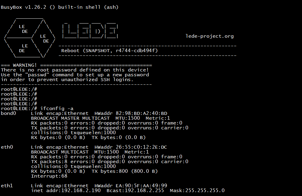
BPI-R2>