Use the debug interface /sys/devices/platform/1000b000.pinctrl/mt_gpio, please refer to script 1
Use the general interface for GPIO: /sys/class/gpio/export and /sys/class/gpio/unexport, please refer to script 2
Script 1 (it can be used on Ubuntu system with kernel 4.4.x)
SYS_FILE=/sys/devices/platform/1000b000.pinctrl/mt_gpio
mt_gpio_mode()
{
   pin=$1
   mode=$2

   if [ ! -f ${SYS_FILE} ]; then
       exit 1
   fi

   echo "mode $pin $mode" > ${SYS_FILE}

   return 0
}

mt_gpio_dir()
{
   pin=$1
   dir=$2

   if [ "x${dir}" == "xout" ]; then
       dir_val=1
   else
       dir_val=0
   fi

   if [ ! -f ${SYS_FILE} ]; then
       exit 1
   fi

   echo "dir $pin $dir_val" > ${SYS_FILE}

   return 0
}

mt_gpio_out()
{
   pin=$1
   out=$2

   if [ ! -f ${SYS_FILE} ]; then
       exit 1
   fi

   echo "out $pin $out" > ${SYS_FILE}

   return 0
}

mt_gpio_in()
{
   pin=$1

   if [ ! -f ${SYS_FILE} ]; then
       exit 1
   fi

   echo "start $1" > ${SYS_FILE}
   result=`cat ${SYS_FILE} | grep "$1"`

   if [ "x${result}" == "x" ]; then
       echo "can't get $pin status"
       exit 2
   fi
   echo ${result}
   pin_val=`echo ${result} | awk -F ' |-' '{print $5}'`
   if [ ${pin_val} == "0" ] ; then
       return 0
   else
       return 1
   fi

   return 0

}
Script 2 (it can be used on Ubuntu system with kernel 4.4.x, and lede with kernel 4.9.x)
#!/bin/ash

DIR=/sys/class/gpio/

global_gpio_offset=0

mt_gpio_init()
{
    pin=$1

    EXPORT=/sys/class/gpio/export
    UNEXPORT=/sys/class/gpio/unexport


    name=`ls $DIR | grep chip`
    if [ x${name} != x ]; then
        echo "chip id : $name"
    else
        echo "No available gpio chip"
        exit 1
    fi

    base=`cat ${DIR}/${name}/base`

    gpio_offset=`echo $((base+$pin))`
    global_gpio_offset=$gpio_offset

    if [ -d ${DIR}/gpio${gpio_offset} ]; then
        return 0
    else
        echo ${gpio_offset} > ${EXPORT}
    fi
}

mt_gpio_init $1

if [ $2 == 'dir' ]; then
    if [ $3 == 'out' ]; then
        echo out > ${DIR}/gpio${global_gpio_offset}/direction
    else
        echo in > ${DIR}/gpio${global_gpio_offset}/direction
    fi
elif [ $2 == 'val' ]; then
    if [ $# == 2 ]; then
        cat ${DIR}/gpio${global_gpio_offset}/value
    elif [ $# == 3 ]; then
        echo $3 >  ${DIR}/gpio${global_gpio_offset}/value
    fi
fi
Hi, I was missing support in WiringPi for BPI R2 so I forked @chaotaklon repo from this post and I added support for GPIO for now. I tested few GPIO ports and it works fine. I also had to fix port mapping.
When you use wiringPiSetup(), you can use ports from column wPi from gpio readall or you can use physical pin numbering by calling wiringPiSetupPhys().
why do you try to set direction of i2c pins? do you want i2c function or not? if not you have to disable i2c0 ( 11007000.i2c) in dts. imho it is not possible to change function in running system
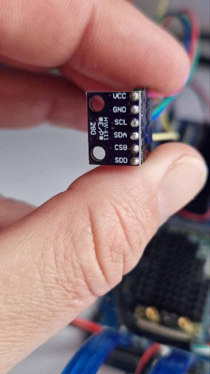
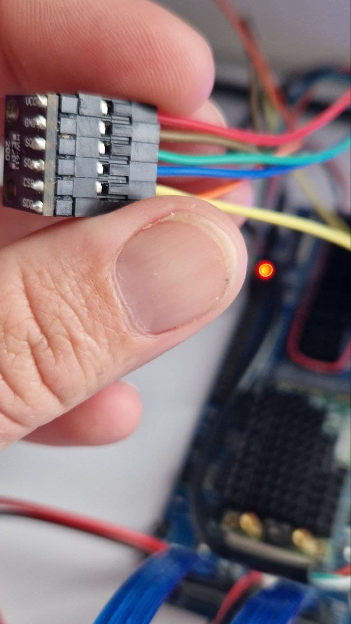
I do require I2C. And this all is just an effort to find out what is wrong, because when I take a multimetter between PIN#1 and GND, I do not measure any voltage. Secondly, While having BMP280 wired correctly (it works on my old RouterStations as well as on OrangePi One+ units I have), it is not detected and I can’t read temperature and pressure.
I am not certain if I2C works at all in this regard, and I am puzzled why I do not measure 3.3V on designated PINs as I should. What is also confusing is that the PIN numbering and GPIO naming is very different (but I found my way to identify pins).
So no, I do not need to disable I2C. I need to make it working.
I do know already that I2C0 is designated to mediatek hdmi. But I do not register the BMP280 on I2C1 or I2C2.
As for I2C - yes, I do realize that it is mapped to i2c1, that is not the problem.
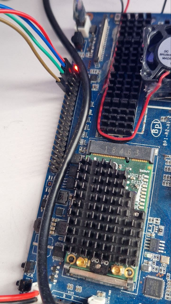
As for voltage - that is actually what I was dealing with - I can’t measure 3.3V on dedicated pins.
There is nothing on those pins (#1, #17). I mean - the voltage fluctuates between -0.2V and +0.2V.
Just to check - having SATA ports pointing to the ground (down), GPIO pinouts on the left - PIN#1 is topmost left pin, right? Topmost right is 5V, correct?
The problem is that I do not measure 3.3V or 5V on either pins.