[BPI-R64] PWM-support

Hi

I start a new thread to collect current state for pwm-support

Afair only pwm7 (on gpio header) was defined in dts and can be used from userspace. I tried to add the other but can’t get the others working

Had added the other pwms to4.19-r64-main branch,but they were not working so i had disabled them

[BPI-R64] Kernel-Development

[BPI-R64] Kernel-Development

As far as i see patch from sean wang is not yet merged to 5.7

For blinking issue i’ve found this,but it seems that there is no v3 https://patchwork.kernel.org/patch/11417611/

I am trying to keep the MT7622 and DRAM chips cooler using a 5V fan (extracted from an old laptap). Can someone help me how to control the fan speed using PWM? I have hooked the fan to the fan socket (which is besides the WPS switch), but presently it runs at full speed. The schematic shows FAN_OUT has different labels: GPIO97/PWM_CH3/TXD4 or G12, PWM3 I don’t know exactly how to try out different PWM duty cycles from the command line. I will eventually do it programatically.

Could someone from @sinovoip team provide some guidance? I have tried reading the Documentation/devicetree/** to gain some understanding about what is coded in the DTS sources. But so far I am deep in the weeds.

https://wiki.fw-web.de/doku.php?id=en:bpi-r2:gpio#pwm

But for this the pwms have to be defined the right way in dts… for first try you can add the pwm3 definition to your dts and change the pinctl to the new one

https://git.kernel.org/pub/scm/linux/kernel/git/stable/linux.git/tree/arch/arm64/boot/dts/mediatek/mt7622-bananapi-bpi-r64.dts?h=linux-5.4.y#n486

As far as i see i missed pwm3…

So from pinctrl definitions in

https://git.kernel.org/pub/scm/linux/kernel/git/stable/linux.git/tree/drivers/pinctrl/mediatek/pinctrl-mt7622.c?h=linux-5.4.y#n401

static int mt7622_pwm_ch3_0_pins[] = { 53, };
static int mt7622_pwm_ch3_0_funcs[] = { 3, };
static int mt7622_pwm_ch3_1_pins[] = { 75, };
static int mt7622_pwm_ch3_1_funcs[] = { 4, };
static int mt7622_pwm_ch3_2_pins[] = { 97, };
static int mt7622_pwm_ch3_2_funcs[] = { 0, };
	PINCTRL_PIN_GROUP("pwm_ch3_0", mt7622_pwm_ch3_0),
	PINCTRL_PIN_GROUP("pwm_ch3_1", mt7622_pwm_ch3_1),
	PINCTRL_PIN_GROUP("pwm_ch3_2", mt7622_pwm_ch3_2),

You can define this (and maybe change last number of “groups” property) near the existing pwm7_pins

pwm3_pins: pwm3-0-pins {
    mux {
        function = "pwm";
        groups = "pwm_ch3_0";
    };
};

And then change pwm7_pins in the inherited pwm-node to the new pwm3_pins

i have added pins to my 5.7-main branch so you need only replace pwm7_pins with pwm3_pins and recompile/install

Frank, I am beginning to get some handle on understanding the DTS entries for pio/pwm1-2-pins node, pwm node in mt7622-bananapi-bpi-r64.dts. I looked at the commit you pointed to above (b14047742a29e6c05c212ccf12de415590bac090). I understand to recompile the DTS using pwm3_pins in mt7622-bananapi-bpi-r64.dts, like so:

&pwm {
	pinctrl-names = "default";
	/* pinctrl-0 = <&pwm7_pins>; */
    pinctrl-0 = <&pwm3_pins>;
	status = "okay";
};

But I am confused about one thing: pwm_ch3 has three modes, as can be seen in drivers/pinctrl/mediatek/pinctrl-mt7622.c

static int mt7622_pwm_ch3_0_pins[] = { 53, };
static int mt7622_pwm_ch3_0_funcs[] = { 3, };
static int mt7622_pwm_ch3_1_pins[] = { 75, };
static int mt7622_pwm_ch3_1_funcs[] = { 4, };
static int mt7622_pwm_ch3_2_pins[] = { 97, };
static int mt7622_pwm_ch3_2_funcs[] = { 0, };

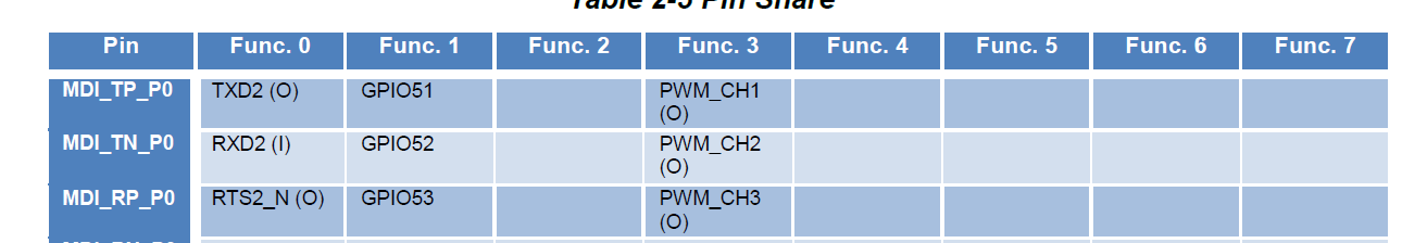
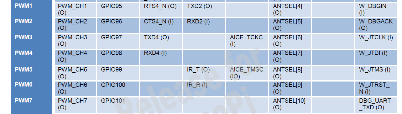
which I interpret to pwm_ch3 is driven to GPIO97 for function mode 0, it is driven to GPIO75 in function mode 4 and to GPIO53 in function mode 3. This matches with the table 2.5 in “section 2.3.1 Pin share scheme” in the MT7622A_Datasheet_for_BananaPi_Only(1).pdf

So my question is: when I replace pwm7_pins with pwm3_pins with the definition

	pwm3_pins: pwm3-pins {
		mux {
			function = "pwm";
			groups = "pwm_ch3_0"; /*mt7622_pwm_ch3_0_pins[] = { 53, };*/
		};
	};

The PWM3 will be driven to GPIO53 correct? 
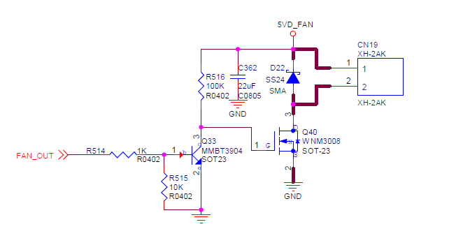
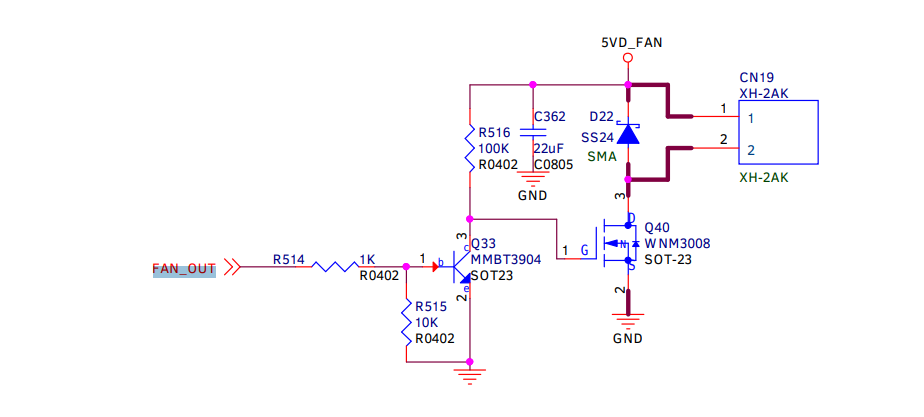
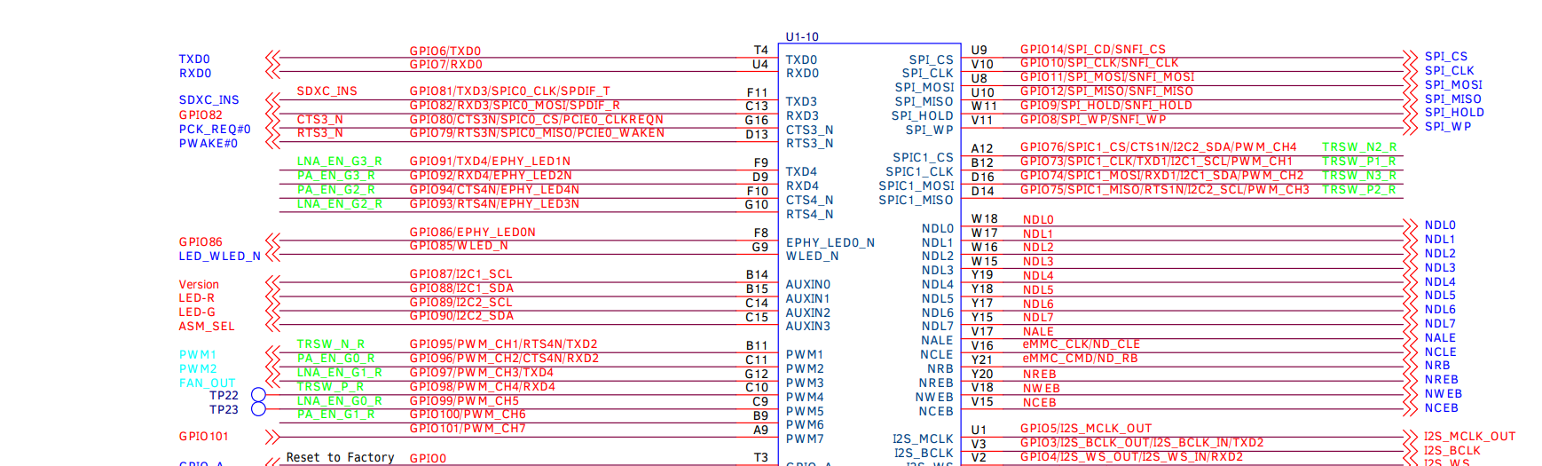
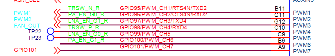
Whereas in the schematic, the FAN_OUT is connected to GPIO97

So I am wondering if we should use groups = “pwm_ch3_2” In fact, I would say, instead of using groups = “pwm_chX_0” for pwmX_pins, it should be “pwm_chX_2” (for pwm 1,2,3,5,7) or “pwm_chX_3” (for pwm 4,6) to get the PWM generated on GPIO95…GPIO101

1 Like

For pwm i guess you’re right…it should be pwm_ch3_2

edit: updated pin defines based on your documentation and amended commit/force-pushed to have no wrong commit

now you can try changing the pwm7_pins to pwm3_pins, if it works we are on the right way :wink: and need only know how to define the pwm-node to use all pwms without changing the pwm-node itself everytime. in 4.19 i tried defining subnodes which seems to be wrong…maybe the right way is defining only multiple pinctrl-x like this (default have to be there as stated in documentation, so i set name of first=pwm1 to default)

&pwm {
        pinctrl-names = "default","pwm2","pwm3","pwm4","pwm5","pwm6","pwm7";
        pinctrl-0 = <&pwm1_pins>;
        pinctrl-1 = <&pwm2_pins>;
        pinctrl-2 = <&pwm3_pins>;
        pinctrl-3 = <&pwm4_pins>;
        pinctrl-4 = <&pwm5_pins>;
        pinctrl-5 = <&pwm6_pins>;
        pinctrl-6 = <&pwm7_pins>;
        status = "okay";
};

Vs.

&pwm {
	status = "okay";
        pinctrl-names = "default";

	pwm1 {
		pinctrl-0 = <&pwm1_pins>;
	};
	pwm2 {
		pinctrl-0 = <&pwm2_pins>;
	};
	pwm4 {
		pinctrl-0 = <&pwm4_pins>;
	};
	pwm5 {
		pinctrl-0 = <&pwm5_pins>;
	};
	pwm6 {
		pinctrl-0 = <&pwm6_pins>;
	};
	pwm7 {
		pinctrl-0 = <&pwm7_pins>;
	};
};

Hi frank…

There is no PWM7 for mt7622. It’s a typo in datasheet, thanks.

  PWM1: GPIO95
  PWM2: GPIO96
  PWM3: GPIO97
  PWM4: GPIO98
  PWM5: GPIO99
  PWM6: GPIO100

  PWM7: GPIO101 (X) <--it's a typo

? Pwm7 is defined by default in mainline dts…it meant to be pwm6 if start counting by 0 (7th pwm). And there are many typos (also pinctl and in pinctl.c)

Main problem we have is how to modify the pwm node to use multiple pwm (currently only 1 pinctl can be used).

@frank-w, i independently tried exactly the same thing as you did by defining the extra pinctrl. Only thing was that i tried only two: pinctrl-0 = <&pwm3_pins>; pinctrl-1 = <&pwm1_pins>. I chose pwm1 because that is connected to the 40pin header, so i was planning to try using a regular LED on a breadboard and a series resistor to test PWM duty cycles. iI have not tested it yet. However the fan_out that should have been driven by pinctrl-0 is not showing any response to change of duty cycle and period. The fan keeps running at full speed no matter how large i make the period (tried 1khz all the way down to 0.25hz, with duty cycles from 50% down to 1%). I expected fan to stop running at the very low duty cycles.

@moore, keeping aside the confusion of pwm7 present or absent, could you show an example DTS code for getting the FAN_OUT control to modulate the fan speed.

Have you tried with only pwm3? So only changing the existing pinctrl?

Have you enabled pwm from userspace like described in my wiki?

No, haven’t tried with only pwm3. Yes, i am enabling pwm using the following sequence:

cd /sys/class/pwm/pwmchip0
echo 0> export
cd pwm0
echo 5000 > duty_cycle
echo 1000000 > period
echo 1>enable

Duty cycle is tiny compared to period. So i expect fan to turn off. But it keeps running at full speed.

Is it working for you?

Why echo 0/pwm0? You guess because you defined it as first (pinctl0)? Could you try pwm3 (maybe 2 because counting starts at 0).

Have currently not much time for the setup and no oscilloscope to verify output

If you want to use this pin as PWM channel 3
GPIO97/PWM_CH3/…
and also use this pin as PWM channel 1 in the same time
GPIO95/PWM_CH1/…

===
Pinctrl driver declared that:
static int mt7622_pwm_ch3_2_pins[] = { 97, };
static int mt7622_pwm_ch1_2_pins[] = { 95, };

We can config pinmux of both pins as pwm mode in the dts

	pwm_pins: pwm1-pwm3-pins {
		mux {
			function = "pwm";
			groups = "pwm_ch3_2", "pwm_ch1_2";
		};
	};
&pwm {
	pinctrl-names = "default";
	pinctrl-0 = <&pwm_pins>;
	status = "okay";
};

use pwm1 like: (linux pwm is starting from 0)

cd /sys/class/pwm/pwmchip0
echo 0> export
cd pwm0
echo 5000 > duty_cycle
echo 1000000 > period
echo 1 > enable

use pwm3 like: (linux pwm is starting from 0)

cd /sys/class/pwm/pwmchip0
echo 2> export
cd pwm2
echo 5000 > duty_cycle
echo 1000000 > period
echo 1 > enable
1 Like

Oh we can use different pinctl in one node…nice. does order matters? Is the first one pwm0 or does linux get the right pwm-num from pinctl definition (so that pwm3 is always pwm2 because of counting from 0)?

The order does not matters, every group in the mux { } will be parsed to pinctrl driver, and switch pin function to the pwm mode.

Linux pwm sysfs use the value of “echo X > export” as hwpwm number X (counting from 0,1,2…),
So if we want to use PWM channel N {N=1,2,3,4,5,6} (bpir64: PWM Channel counting from 1,2,3…),
we can just echo (N-1) to the “export” node under “/sys/class/pwm/pwmchip0”.

static ssize_t export_store(struct device *parent,
			    struct device_attribute *attr,
			    const char *buf, size_t len)
{
	struct pwm_chip *chip = dev_get_drvdata(parent);
	struct pwm_device *pwm;
	unsigned int hwpwm;
	int ret;

	ret = kstrtouint(buf, 0, &hwpwm);
	if (ret < 0)
		return ret;

	if (hwpwm >= chip->npwm)
		return -ENODEV;

	pwm = pwm_request_from_chip(chip, hwpwm, "sysfs");
...
}

have changed my dts like you’ve mentioned

do i need your pwm-clock-Patch https://patchwork.kernel.org/patch/11417611/ (v2 because there is not yet a v3) to get led-blinking? the param i write in userspace is still in nanoseconds, right?

for pwm2 (1) i get write error…maybe it’s blocked by another function

root@bpi-r64:~# cd /sys/class/pwm/pwmchip0
root@bpi-r64:/sys/class/pwm/pwmchip0# echo 0> export

root@bpi-r64:/sys/class/pwm/pwmchip0# echo 1> export                                                                          
-bash: echo: write error: Invalid argument
root@bpi-r64:/sys/class/pwm/pwmchip0# echo 2> export                                                                          

root@bpi-r64:/sys/class/pwm/pwmchip0# echo 3> export                                                                          

root@bpi-r64:/sys/class/pwm/pwmchip0# echo 4> export                                                                          

root@bpi-r64:/sys/class/pwm/pwmchip0# echo 5> export                                                                          

root@bpi-r64:/sys/class/pwm/pwmchip0# echo 6> export                                                                          

root@bpi-r64:/sys/class/pwm/pwmchip0#

and export does not create any nodes:

root@bpi-r64:/sys/class/pwm/pwmchip0# echo 5000 > pwm0/duty_cycle
-bash: pwm0/duty_cycle: No such file or directory
root@bpi-r64:/sys/class/pwm/pwmchip0# ls
device  export  npwm  power  subsystem  uevent  unexport

found my error…pwm-number have to be string :wink: else number will be interpreted by bash as input-descriptor (1=stdout, 2=stderr, upper user-defined)

root@bpi-r64:/sys/class/pwm/pwmchip0# echo "1"> export                                                                        
root@bpi-r64:/sys/class/pwm/pwmchip0# echo "2"> export                                                                        
root@bpi-r64:/sys/class/pwm/pwmchip0# echo "3"> export                                                                        
root@bpi-r64:/sys/class/pwm/pwmchip0# echo "4"> export                                                                        
root@bpi-r64:/sys/class/pwm/pwmchip0# echo "5"> export                                                                        
root@bpi-r64:/sys/class/pwm/pwmchip0# echo "6"> export                                                                        
root@bpi-r64:/sys/class/pwm/pwmchip0# ls
device  npwm   pwm0  pwm2  pwm4  pwm6       uevent
export  power  pwm1  pwm3  pwm5  subsystem  unexport

btw. echo 0 is basicly wrong…echo “1” creates pwm0…i guess this is what sam wants to say :slight_smile:

The above few email responses were very encouraging and I was excited to try it out. Unfortunately, I still did not get success. @frank-w, I also did the similar thing as you did, except removed pwm7 from the list. I do see pwm0…pwm5 nodes created in pwmchip0 as shown below. For completeness, these are my DTS entries related to PWM:

    >>>>>  mt7622.dtsi <<<<<
     pwm: pwm@11006000 {
	compatible = "mediatek,mt7622-pwm";
	reg = <0 0x11006000 0 0x1000>;
	interrupts = <GIC_SPI 77 IRQ_TYPE_LEVEL_LOW>;
	clocks = <&topckgen CLK_TOP_PWM_SEL>,
		 <&pericfg CLK_PERI_PWM_PD>,
		 <&pericfg CLK_PERI_PWM1_PD>,
		 <&pericfg CLK_PERI_PWM2_PD>,
		 <&pericfg CLK_PERI_PWM3_PD>,
		 <&pericfg CLK_PERI_PWM4_PD>,
		 <&pericfg CLK_PERI_PWM5_PD>,
		 <&pericfg CLK_PERI_PWM6_PD>;
	clock-names = "top", "main", "pwm1", "pwm2", "pwm3", "pwm4",
		      "pwm5", "pwm6";
	status = "disabled";
};
  
>>>>>  mt7622-bananapi-bpi-r64.dts <<<<<< 
    pwm_pins: pwm1-pwm6-pins {  /* inside node pio */
	mux {
		function = "pwm";
		groups = "pwm_ch1_2", "pwm_ch2_2", "pwm_ch3_2", "pwm_ch4_3", "pwm_ch5_2", "pwm_ch6_3"; /* GPIO 95..100 */
	};
};
.....
&pwm {
    pinctrl-names = "default";
    pinctrl-0 = <&pwm_pins>;
    status = "okay";
};

After compiling and transferring the DTB to R64 board and booting system, I ran the following commands:

root> cd /sys/class/pwm/pwmchip0
root> echo 0 > export
root> echo 2 > export
root> ls
device  export  npwm  power  pwm0  pwm2  subsystem  uevent  unexport
root> cd pwm2
root> echo 40000000 > period
root> echo 400 > duty_cycle
root> echo 1 > enable
root> cat period
40000000
root> cat duty_cycle
400

But there is no change in fan speed. Acutally, fan runs at full speed even before booting – right when the power is plugged in. So I do not understand how FAN_OUT pin is getting set at high value so as to drive the Q33 and Q40 transistor into ON state (figuratively speaking) image

Or you could have separated the number and “>” like so: echo 1 > export – then there is no difference between echo 1 and echo "1"

as i have no fan and no oscilliscope, i tried the led-way on pwm1 (=pwm0 in linux, pins 9+11 on gpio-header)

root@bpi-r64:/sys/class/pwm/pwmchip0/pwm0# echo 10000 > period
root@bpi-r64:/sys/class/pwm/pwmchip0/pwm0# echo 5000 > duty_cycle 
root@bpi-r64:/sys/class/pwm/pwmchip0/pwm0# echo 1 > enable

as duty-cycle is half of period i had expected that led is half so bright as before…but no change

Do you get any pinctrl error message with ‘dmesg’ command ?
Maybe some other dts nodes block the pinmux selection of pwm pins ?