Hello again @frank-w, I could not achieve building the kernel 4.14 with Ubuntu. Hence, XPT2046 screen is not working, the system does not read config.txt for SPI connection. However, I used your GPIO codes from your wiki for blinking leds using java code to integrate our project. Very good information. Moreover, Debian build for Banana-Pi R2 is without interface and it also does not contain config.txt in /boot. Therefore, SPI is not enabled. Also, we can’t try XPT2046 screen in Debian as Debian build starts with terminal. I need to use that touch screen with Banana-Pi. Could you recommend further details about that issue?
Config.txt is raspbian-specific…what do you want to try here? You need to build kernel with changed dta matching the driver for tft. Also my debian/ubuntu are basic images…you have to install xserver + displaymanager by your own. Most users don’t want xserver on router.
I need working SPI connection for using XPT2046 screen. Do you recommend anything else? Could you compile the kernel again and make SPI working in Ubuntu?
as i said multiple times, i cannot build a kernel for a specific spi-device and i cannot test spi except looking if spidev-device comes up because of missing device
add driver-section to dts, add your driver in menuconfig and compile kernel
i take a dts for a display with same driver from beagleboard and modified some positions:
/dts-v1/;
/plugin/;

/ {
	"bananapi,bpi-r2", "mediatek,mt7623";

	/* identification */
	part-number = "BB-ADS7846";
	version = "00A0";

        /* state the resources this cape uses */
        exclusive-use =
                /* the pin header uses */
                "P9.17",        /* SPI0_CS0 */
                "P9.18",        /* SPI0_D1 */
                "P9.21",        /* SPI0_D0 */
                "P9.22",        /* SPI0_SCLK */
                "P9.23";       /* pendown */

	fragment@0 {
		target = <&pio>;
		__overlay__ {
		 ads7846_pins:pinmux_spi0_pins {
				pinctrl-single,pins = <
        	0x150 0x30 /* spi0_sclk, INPUT_PULLUP | MODE0 */
        	0x154 0x10 /* spi0_d0, OUTPUT_PULLUP | MODE0 */
        	0x158 0x30 /* spi0_d1, INPUT_PULLUP | MODE0 */
        	/* For ADS7846 */
	        0x15c 0x10 /* spi0_cs0, OUTPUT_PULLUP | MODE0 */
				>;
			};
		};
};

	fragment@1 {
		target = <&spi0>;
		__overlay__ {
			#address-cells = <0x1>;
	     	        #size-cells = <0>;
			status = "okay";
			pinctrl-names = "default";
			pinctrl-0 = <&ads7846_pins>;/*maybe use spi0_pins_a here and remove fragment@0*/
			ti,pindir-d0-out-d1-in = <1>;
 		    ads7846@0 {
				compatible = "ti,ads7846";
				spi-max-frequency = <100000>;   /* Higher frequency causes more jitter */
				interrupts = <17 0>;             /* pin number 17 and falling edge interrupt */
				interrupt-parent = <&gpio1>;
				pendown-gpio = <&gpio1 17 0>;        /* This corresponds to pin no 23 = GPIO1[17]*/
				reg = <0>;     /* We are using chip select 0, so we enter 0 here */
                #addr-size = <2>;
                #page-size = <32>;

                /* driver defaults */
                ti,x-min = /bits/ 16 <0xB0>;
                ti,y-min = /bits/ 16 <0x231>;
                ti,x-max = /bits/ 16 <0xF49>;
                ti,y-max = /bits/ 16 <0xF6B>;
                ti,pressure-min = /bits/ 16 <0>;
                ti,pressure-max = /bits/ 16 <0xFF>;
                ti,x-plate-ohms = /bits/ 16 <0x96>;
                ti,swap_xy = /bits/ 16 <0>;
                ti,keep_vref_on = /bits/ 16 <0>;
                ti,cs = /bits/ 16 <1>;
    		    linux,wakeup;
	        };
        };
    };
};
here you can try skip the fragment@0 where i don’t know the pin-configuration, but spi0 has already a pin-definition (maybe not there on beagleboard), which is defined this way:
spi0_pins_a: spi@0 {
	pins_spi {
		pinmux = <MT7623_PIN_53_SPI0_CSN_FUNC_SPI0_CS>,
			<MT7623_PIN_54_SPI0_CK_FUNC_SPI0_CK>,
			<MT7623_PIN_55_SPI0_MI_FUNC_SPI0_MI>,
			<MT7623_PIN_56_SPI0_MO_FUNC_SPI0_MO>;
		bias-disable;
	};
};
i don’t know how to configure gpio inside the spi-driver-part.
and don’t forget driver in menuconfig (ads7846)
@frank-w, thank you again for your detailed information. I finally compiled Ubuntu 4.14 bpi-r2 kernel in Banana Pi R2 with Ubuntu 16.04 system with adding your dts code. Later, I updated grub and grub2. However, the system is still in kernel 4.4.70. I think it’s because of the architecture difference. The architecture is ARMv7, not x86 or x64. How can I boot the system with the new kernel?
One more question, I found out that you compiled Raspbian for Banana-Pi. Your link. XPT2046 touch screen works in Raspbian system in Raspberry. Are SPI and GPIO working in Banana-Pi with your built Raspbian system? Could the screen work in Raspbian in Banana-Pi?
raspian ist not from me…only debian stretch and ubuntu 18.4 from my gdrive
there is no grub…only uboot
after copy kernel+modules to your card you have to say uboot that you warnt to boot this file by changing the kernel-variable in uEnv.txt
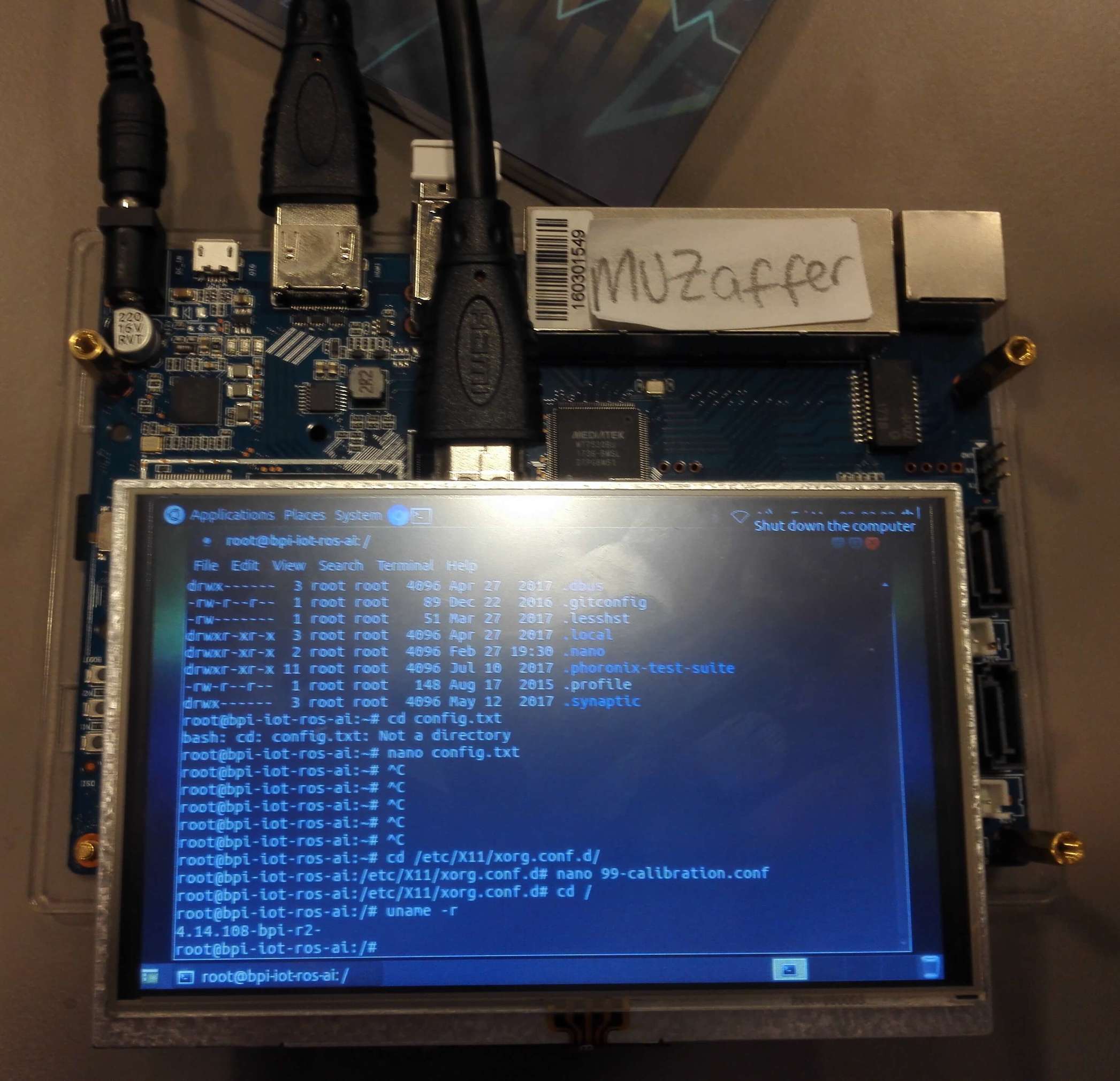
Hello @frank-w, I successfully compiled 4.14.108-bpi-r2 kernel using your /dts-v1/ file and I checked monitor settings in menuconfig before compiling in Ubuntu and it works. I reinstalled the driver from link. However, touch still does not working. Moreover, I did not understand where should I insert the code spi0_pins_a: spi@0
1 Like
You have changed bpi-r2.dts or using my overlay? If using overlay how do you load it? Have you verified dts from linux (sysfs devicetree)?
How do you define the gpio-properties?
@Ryder.Lee can you guide @sanalcem to get spi working?
Hi,
does anyone have a working xpt2046 touchscreen with kernel 5.10?
A TS with stmpe610 is working fine with Debian Bullseye and frank-w Kernel 5.10. But after switching to an ads7846 no touch interrupts are recongized. I watched the interrupts with a scope and they are ok.
Device tree changes (mostly taken from this thread):
&spi0 {
    ads7846@1 {
        #address-cells = <1>;
        #size-cells = <0>;
        compatible = "ti,ads7846";
        reg = <1>;     // CS1
        cs-gpios = <&pio 20 GPIO_ACTIVE_LOW>;
        interrupt-parent = <&pio>;
        interrupts = <GIC_SPI 25 8>;
        pendown-gpio = <&pio 25 8>;
        spi-max-frequency = <100000>;
        #addr-size = <2>;
        #page-size = <32>;
};
I use GPIO 25 (Pin 16) for the Interrupts, just like with the stmpe-ts before. Now I get an interrupt entry in the table, but it never counts interrupts:
cat /proc/interrupts
       CPU0       CPU1       CPU2       CPU3
...
85:          0          0          0          0   mt-eint   0 Edge      ads7846
The “0” before “Edge” makes me wondering, if this has to be the GPIO nr? If I omit the “GIC_SPI” from the “interrupts” entry, I get the GPIO nr there, but still no interrupts. I guess, that is, because the “interrupts” entry is evaluated by the interrupt-controller (&pio) and that needs the “GIC_SPI”, while the ads7846 driver only knows 2-cell-interrupt nodes. But I didn’t see, where the latter accesses this node. Does anyone have an idea of needed changes or where to observe something?
Stephan