following this and other posts:
I got curious whenever it is possible to use multiple fans for intake? I.e. two NF-A4x10 5V PWM . The first covering the Mediatek and the second the Mini PICe slot.
I plan to cut, using a water jet cutter, outtake slots in the cover of the case above the SD and SIM slots.
To move the heat away from the chips I am searching for properly sized copper or aluminum cooler bodies. Many thanks in advance for your feedback!
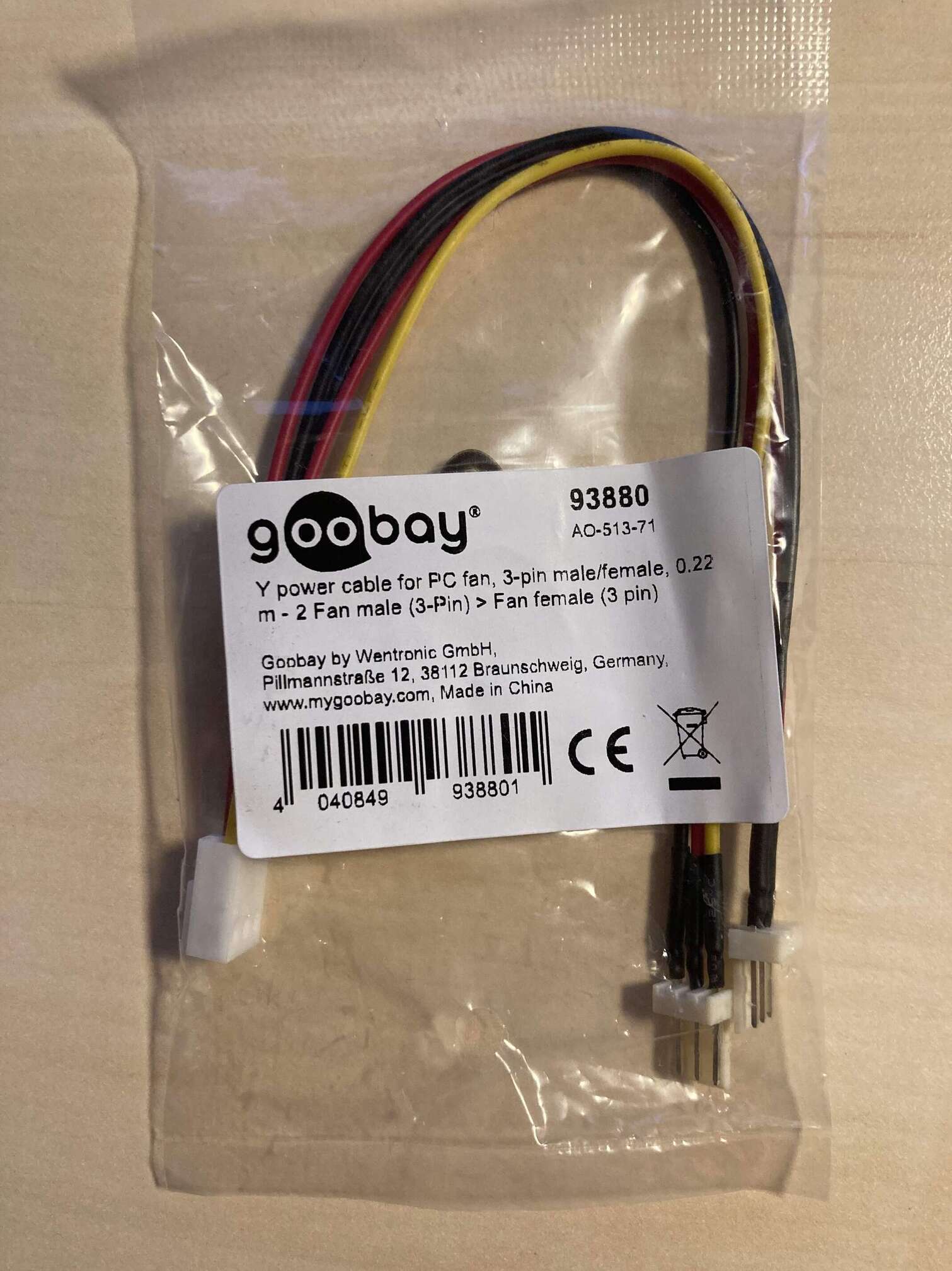
the Noctua uses a four pol plug. I ordered a 3 Pol Molex for a “stupid” CPU fan but that doesn’t fit into the 3 Pol FAN port either. Do you happen to know which plug is compatible with the FAN?
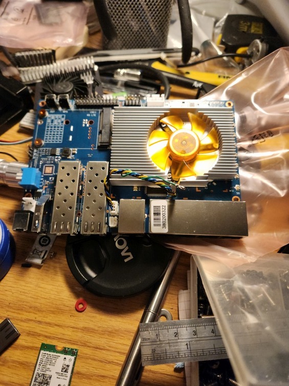
Those fans are probably well over what you need. I used a 50x61x13.8 4000RPM heatsink to cover the switch processor, MK7986, and memory. On the 7975 (wifi chips) side I just placed some passive heatsinks and rotated the heat sink with the fan so air channeled would blow across them.
The fan I had to cut the provided connector on and crimp a new JST PH connector (used the 3 pin even though the fan I used wasn’t PWM capable).
End result is that it’s very quiet, heat sinks are not even warm to the touch, and power consumption as increased < 1 watt.
Better to have than to need No, honestly, I searched for the best fitting option with a low profile and since Noctua is a well established brand it was the first I found.
For the heat sinks I opted for copper since it’s been stated they are better for active cooling due to a significantly higher thermal conductivity compared to aluminum (231 vs. 136).
I’ve put on the original Aliexpress variant and plastered all the board withKaneka RV089 elastomer, I mean. . It is a router not a 300W+ Intel CPU. It also does not need top notch thermal 15W/mK+ thermal pads that are most fake anyways.
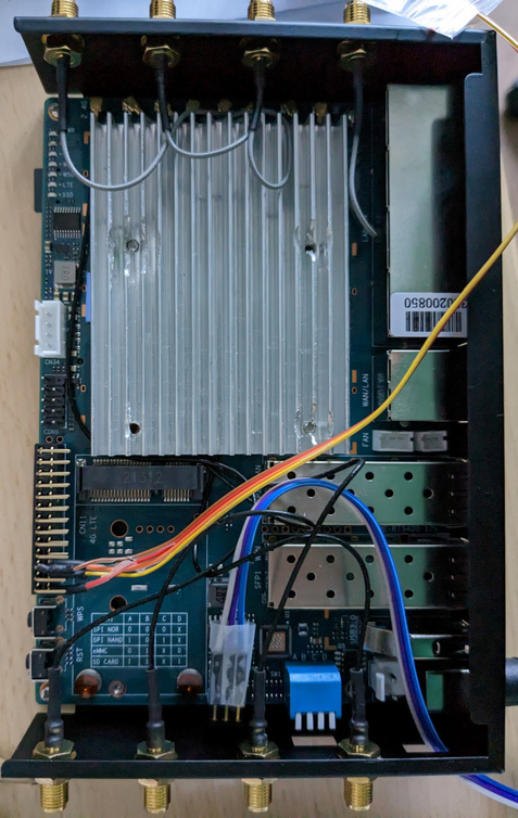
If the board is not in a case you do not need any heatsinks/fan. One problem i see is the metal case as it has no ventilation holes. Thinking whats the best way to add them without expert equipment here…drilling holes with home equipment will deform the plates
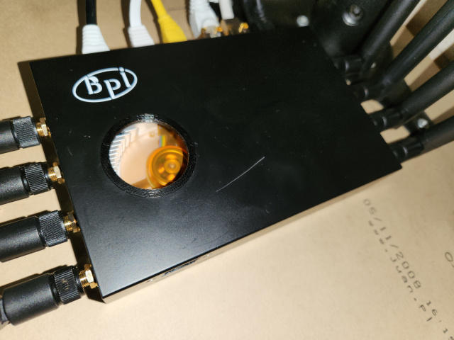
Nope, it just matters how straight your hands are. Just drill it on disposable wood support, slowly. I’ve 3d printed a ring for mesh. Still haven’t found out where I have put those sheets to glue on the ring. It will look pretty factory like.
For exhausts you can drill few 10mm holes above the reset/WPA buttons.
@frank-w I think it’s not a 2.5 mm but 3.5mm JST-PH connector. measuring with a caliper the dimension is far of 2.5. Searching for 3.5mm variant surprisingly brought this one up kind of double confirming my assumption, doesn’t it?
I drilled many holes with a little trick to prevent any bending. Just put some wood behind the metal as a counter surface. For the big fan hole I drilled a few large holes and filed it to the required diameter.
You cannot have 50% tolerances when the plug has a 2mm pitch.
Not sure where is the problem? Get a JST PH2.0 3 pin cable. Solder it to your fans. For my setup I just needed the 3 pin housing and replace it.
If you need two fans(You don’t really) just use the 2 pin JST for power and feed only one PWM pin from your desired location, from the FAN solder point or make a Y splitter from the 3 pin section.
i’ve wrote 2.0mm which is the pin-spacing (most connectors like gpio/debug-uart has 2.54mm spacing)
i want to use the 3d printed case later too, but need a friend which is in local hackerspace to have access to a 3d-printer. till then i try to make best of the metal case i have already here…
@FerrumMaster you have drilled this hole in 1 step or have you drilled many holes and combined then in any way? looks good so far, but largest drillers i have are 10mm which is far away from the hole needed (>30mm for 40mm fan)
@frank-w I live in Weinheim close to Mannheim / Heidelberg. The quote from the 3D-Printing service in Bensheim was around 60 Euro. For the print we will use heat resistant filament. I just have to clarify the material for the LED Carriers. If you like we can arrange something
About the JST plug I thought the mm dimension was about the actual dimension as I assumed PIN placements are unified … which it isn’t. I will give the 2mm 3-Pole a try than. Thanks for the clarification.
I used a conical drill. I always do use that for metalworks, case I/O holes etc. Just on a leftover wood block, slowly, then nothing bends. Do not let it heat up. Drill to your desired diameter then a Dremel to fine tune the edges.