How can I change path of using by WiringPi?
you mean I can use linux standart C open/read/write-functions for control gpio?
i have no tried it yet, but these are simple “files” which should be opened by these standard-functions
have also not digged into wiring pi but gpio-access itself is similar to raspi…
Can you give a usage example of scripts, please? I couldn’t run the script 2.
script also doesn’t work
chip id : gpiochip233
./example_gpio.sh: line 25: base+: syntax error: operand expected (error token is "+")
./example_gpio.sh: line 31: echo: write error: Invalid argument
./example_gpio.sh: line 37: [: ==: unary operator expected
./example_gpio.sh: line 43: [: ==: unary operator expectedHi, I was missing support in WiringPi for BPI R2 so I forked @chaotaklon repo from this post and I added support for GPIO for now. I tested few GPIO ports and it works fine. I also had to fix port mapping.
When you use wiringPiSetup(), you can use ports from column wPi from gpio readall or you can use physical pin numbering by calling wiringPiSetupPhys().
+-----+-----+---------+------+---+---Pi ?---+---+------+---------+-----+-----+
| BCM | wPi |   Name  | Mode | V | Physical | V | Mode | Name    | wPi | BCM |
+-----+-----+---------+------+---+----++----+---+------+---------+-----+-----+
|     |     |    3.3v |      |   |  1 || 2  |   |      | 5v      |     |     |
|  75 |   8 |   SDA.1 |  OUT | 1 |  3 || 4  |   |      | 5v      |     |     |
|  76 |   9 |   SCL.1 |   IN | 1 |  5 || 6  |   |      | 0v      |     |     |
| 206 |   7 | GPIO. 7 |   IN | 0 |  7 || 8  | 1 | ALT3 | TxD     | 15  | 82  |
|     |     |      0v |      |   |  9 || 10 | 0 | ALT0 | RxD     | 16  | 81  |
|  80 |   0 | GPIO. 0 | ALT3 | 1 | 11 || 12 | 1 | ALT5 | GPIO. 1 | 1   | 74  |
|  79 |   2 | GPIO. 2 |   IN | 1 | 13 || 14 |   |      | 0v      |     |     |
| 205 |   3 | GPIO. 3 |   IN | 0 | 15 || 16 | 1 | OUT  | GPIO. 4 | 4   | 25  |
|     |     |    3.3v |      |   | 17 || 18 | 0 | OUT  | GPIO. 5 | 5   | 24  |
|  56 |  12 |    MOSI |  OUT | 0 | 19 || 20 |   |      | 0v      |     |     |
|  55 |  13 |    MISO |   IN | 1 | 21 || 22 | 1 | OUT  | GPIO. 6 | 6   | 18  |
|  54 |  14 |    SCLK |   IN | 0 | 23 || 24 | 1 | IN   | CE0     | 10  | 53  |
|     |     |      0v |      |   | 25 || 26 | 1 | IN   | CE1     | 11  | 20  |
|  57 |  30 |   SDA.0 | ALT0 | 1 | 27 || 28 | 1 | ALT5 | SCL.0   | 31  | 58  |
| 126 |  21 | GPIO.21 |   IN | 0 | 29 || 30 |   |      | 0v      |     |     |
| 200 |  22 | GPIO.22 |   IN | 0 | 31 || 32 | 1 | IN   | GPIO.26 | 26  | 21  |
| 126 |  23 | GPIO.23 |   IN | 0 | 33 || 34 |   |      | 0v      |     |     |
|  73 |  24 | GPIO.24 | ALT0 | 1 | 35 || 36 | 0 | OUT  | GPIO.27 | 27  | 19  |
| 202 |  25 | GPIO.25 |   IN | 1 | 37 || 38 | 1 | OUT  | GPIO.28 | 28  | 72  |
|     |     |      0v |      |   | 39 || 40 | 0 | ALT0 | GPIO.29 | 29  | 49  |
+-----+-----+---------+------+---+----++----+---+------+---------+-----+-----+
| BCM | wPi |   Name  | Mode | V | Physical | V | Mode | Name    | wPi | BCM |
+-----+-----+---------+------+---+---Pi ?---+---+------+---------+-----+-----+
I would really appreciate any help. Adding support for PWM, SPI, I2C and other… danielvrsek/BPI-WiringPi2
Here is a link to the datasheet MT7623N_Public_Datasheet_for_Development_Board_v1.1.pdf - Google Drive
To install, you need to download source and run as root ./build
To build your source, add -l wiringPi
g++ -o ../GPIO_LED_test ../GPIO_LED_test.cpp -l wiringPi
It all started by trying to make SPI working… 
1 Like
sr. i’m newbie . i want to ask u : how many Volt output gpio when mode out and value 1 ?
Should be 3.3volt…
1 Like
I am a bit puzzled by this. I am trying to enable 3.3V output, but when I try usually procedure (export, direction, etc…), it self-reboot BPi-R2.
What am I missing? I thought that first 3.3V pin is Pin #1.
Running bellow (trying to enable 3.3V pin #1):
echo 233 > /sys/class/gpio/export
End-up with bellow error in console and logs, requiring to reboot the router:
[ 4408.138498] mt-pmic-pwrap 1000d000.pwrap: unexpected interrupt int=0x2
[ 4408.138529] mt-pmic-pwrap 1000d000.pwrap: unexpected interrupt int=0x2
[ 4408.146395] mt-pmic-pwrap 1000d000.pwrap: unexpected interrupt int=0x2
[ 4408.146408] mt-pmic-pwrap 1000d000.pwrap: unexpected interrupt int=0x2
[ 4408.154349] mt-pmic-pwrap 1000d000.pwrap: unexpected interrupt int=0x2
[ 4408.162338] mt-pmic-pwrap 1000d000.pwrap: unexpected interrupt int=0x2
[ 4408.162366] mt-pmic-pwrap 1000d000.pwrap: unexpected interrupt int=0x2
[ 4408.169970] mt-pmic-pwrap 1000d000.pwrap: unexpected interrupt int=0x2
[ 4408.177560] mt-pmic-pwrap 1000d000.pwrap: unexpected interrupt int=0x2
[ 4408.185127] mt-pmic-pwrap 1000d000.pwrap: unexpected interrupt int=0x2
[ 4408.192701] mt-pmic-pwrap 1000d000.pwrap: unexpected interrupt int=0x2
[ 4408.200301] mt-pmic-pwrap 1000d000.pwrap: unexpected interrupt int=0x2
[ 4408.207980] mt-pmic-pwrap 1000d000.pwrap: unexpected interrupt int=0x2
[ 4408.215883] mt-pmic-pwrap 1000d000.pwrap: unexpected interrupt int=0x2
[ 4408.223456] mt-pmic-pwrap 1000d000.pwrap: unexpected interrupt int=0x2
[ 4408.231055] mt-pmic-pwrap 1000d000.pwrap: unexpected interrupt int=0x2
[ 4408.238648] mt-pmic-pwrap 1000d000.pwrap: unexpected interrupt int=0x2
[ 4408.246219] mt-pmic-pwrap 1000d000.pwrap: unexpected interrupt int=0x2
[ 4408.253856] mt-pmic-pwrap 1000d000.pwrap: unexpected interrupt int=0x2
[ 4408.261811] mt-pmic-pwrap 1000d000.pwrap: unexpected interrupt int=0x2
[ 4408.269746] mt-pmic-pwrap 1000d000.pwrap: unexpected interrupt int=0x2
[ 4408.277706] mt-pmic-pwrap 1000d000.pwrap: unexpected interrupt int=0x2
[ 4408.285612] mt-pmic-pwrap 1000d000.pwrap: unexpected interrupt int=0x2
[ 4408.293226] mt-pmic-pwrap 1000d000.pwrap: unexpected interrupt int=0x2
[ 4408.300839] mt-pmic-pwrap 1000d000.pwrap: unexpected interrupt int=0x2
I have to be missing something.
The 3v3 pins are fixed voltage not switchable. And the other gpio has numbers far above 1
Thanks. That actually helps.
OK, so:
root@ap-unimatrix:/usr/src# cat /sys/kernel/debug/pinctrl/1000b000.pinctrl/pinmux-pins | grep .i2c
pin 57 (SDA1): 11008000.i2c (GPIO UNCLAIMED) function func1 group SDA1
pin 58 (SCL1): 11008000.i2c (GPIO UNCLAIMED) function func1 group SCL1
pin 75 (SDA0): 11007000.i2c (GPIO UNCLAIMED) function func1 group SDA0
pin 76 (SCL0): 11007000.i2c (GPIO UNCLAIMED) function func1 group SCL0
So I need pins 75 and 76 then?
echo 308 > /sys/class/gpio/export
echo 309 > /sys/class/gpio/export
echo out > /sys/class/gpio/gpio308/direction
echo in > /sys/class/gpio/gpio309/direction
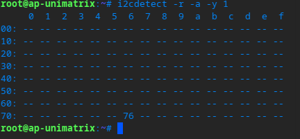
OK, now i2cdetect actually does some detection. At least it is not instant, it goes address by address. We’ll see.
why do you try to set direction of i2c pins? do you want i2c function or not? if not you have to disable i2c0 ( 11007000.i2c) in dts. imho it is not possible to change function in running system
arch/arm/boot/dts/mediatek/mt7623n-bananapi-bpi-r2.dts
disable/drop the
status = "okay";
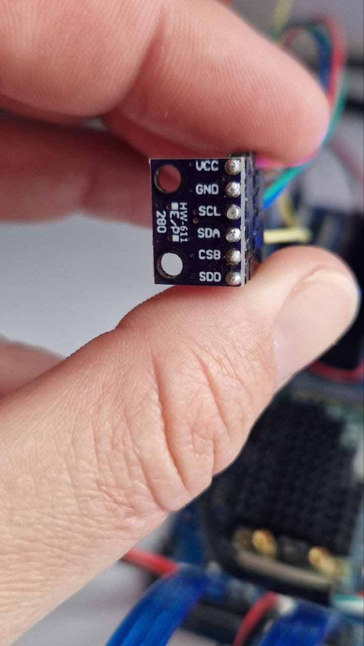
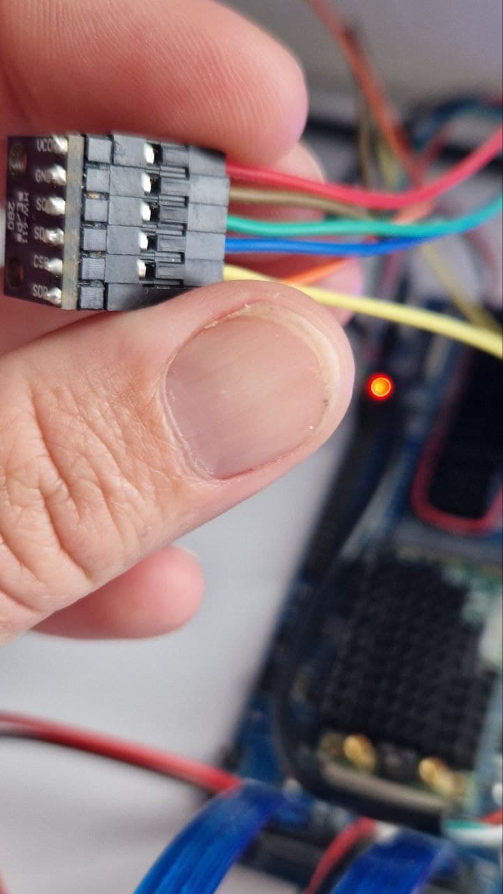
I do require I2C. And this all is just an effort to find out what is wrong, because when I take a multimetter between PIN#1 and GND, I do not measure any voltage. Secondly, While having BMP280 wired correctly (it works on my old RouterStations as well as on OrangePi One+ units I have), it is not detected and I can’t read temperature and pressure.
I am not certain if I2C works at all in this regard, and I am puzzled why I do not measure 3.3V on designated PINs as I should. What is also confusing is that the PIN numbering and GPIO naming is very different (but I found my way to identify pins).
So no, I do not need to disable I2C. I need to make it working.
I do know already that I2C0 is designated to mediatek hdmi. But I do not register the BMP280 on I2C1 or I2C2.
I am clueless now.
I mean soc i2c0 not in system
And then you don’t have to play with gpio direction/export…
i2c0 ( 11007000.i2c) should be visible in dmesg showing you the virtual bus number
I am very sorry, could you please elaborate? As I do not understand. i2c0 is assigned to mediatek hdmi.
I can work with i2c1 or i2c2, doesn’t matter - as long as the BMP will be visible by i2cdetect.
I guess i2c0 is mapped to i2c-bus 1 because hdmi is instatiated earlier and catches virtual i2c0.
Have you correctly powered your device? Have you measured power lines?
The router is powered, as it runs fine.
As for I2C - yes, I do realize that it is mapped to i2c1, that is not the problem.
As for voltage - that is actually what I was dealing with - I can’t measure 3.3V on dedicated pins.
There is nothing on those pins (#1, #17). I mean - the voltage fluctuates between -0.2V and +0.2V.
Just to check - having SATA ports pointing to the ground (down), GPIO pinouts on the left - PIN#1 is topmost left pin, right? Topmost right is 5V, correct?
The problem is that I do not measure 3.3V or 5V on either pins.
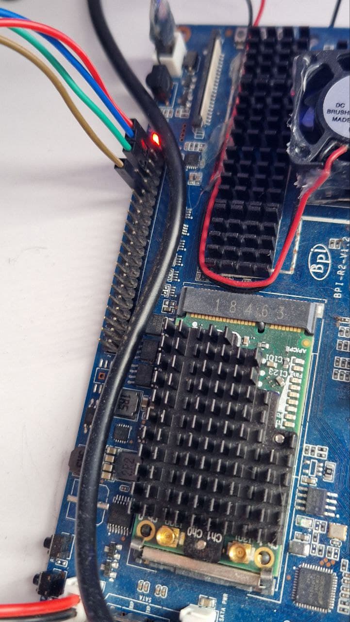
you connected it wrong ![]()
pin1 is the one with small arrow on board near the mpcie slot
1 Like
I wrote before that I had to be missing something. Pin1 marking on the board - classic. Thanks a lot! Would be draining my head, before/if I’d found out much later.
Looks like working now ![]()