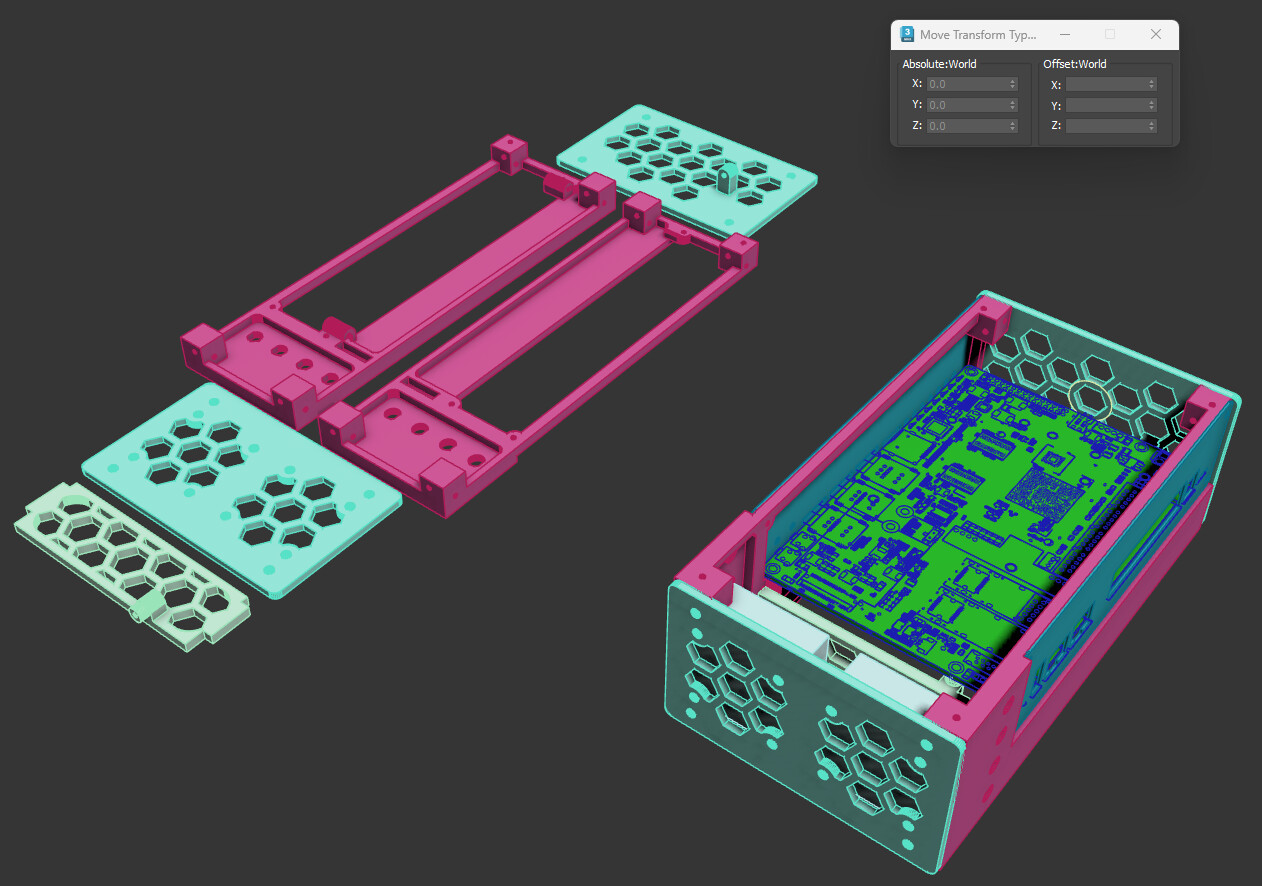
I also don’t quite understand how the antenna compartment is secured to the main body. Is it supposed to be friction fit to the ‘case mount’ part which seems to have corresponding holes?
I was using fdm with petg with FDM, but I believe any filament would be fine. DLP might be a little bit overkill for it. The antenna compartment is secured by a pair of N52 magnets. You might need to modify the design to fit your need.
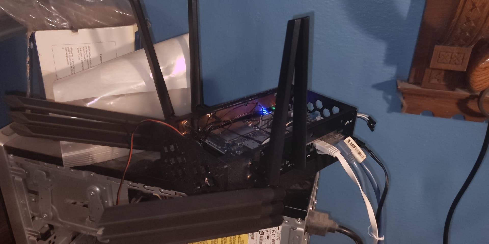
Thank you. I’ve figured out where the magnets go. Would you mind sharing some live photos of the case?
Hej! Any news on the experimental design? I might be able to test it. The vertically placed PCB is innovative and may take advantage of the chimney effect,the natural airflow. But shouldn’t the I/O ports be on the long edge?
This is beautiful, @Sergey_Toroshchin.
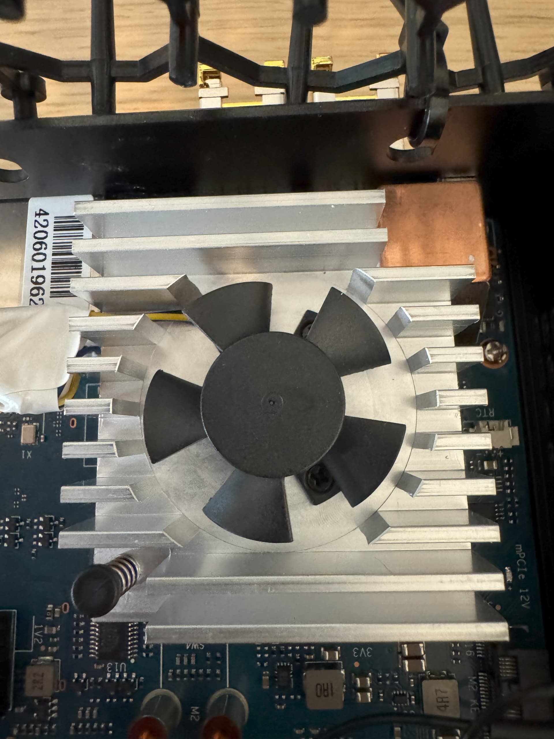
I got okay results, although not as good as yours, putting a passive heat sink on the SoC, and using the stock BPI active cooler on the SFP cages (where the cooling is really needed).
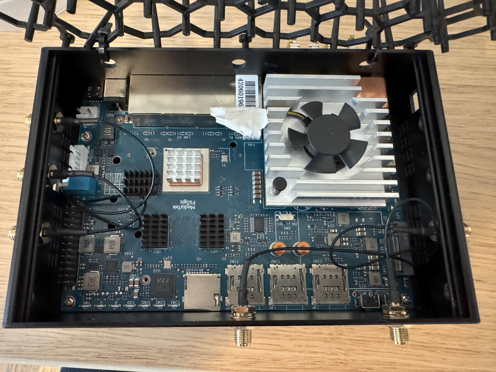
To use the stock cooler on the SFP cages, I moved two of the pigtails from that side of the case to the front. I moved the thermal pads on the stock heat sink around to match up with the SFP cages, and removed one of the plastic pins that was making contact with the WAN cage. I used another small copper heat sink from the same set as the SoC heat sink (with thermal conductive adhesive on the bottom) to secure the surface where I removed the plastic pin to the USB-A housing. They happened to line up perfectly. It was also necessary to use some electrical tape to keep the fan wiring crimped slightly; otherwise, the protective plastic sleeve tends to unbend itself, putting some torque on the heat sink.
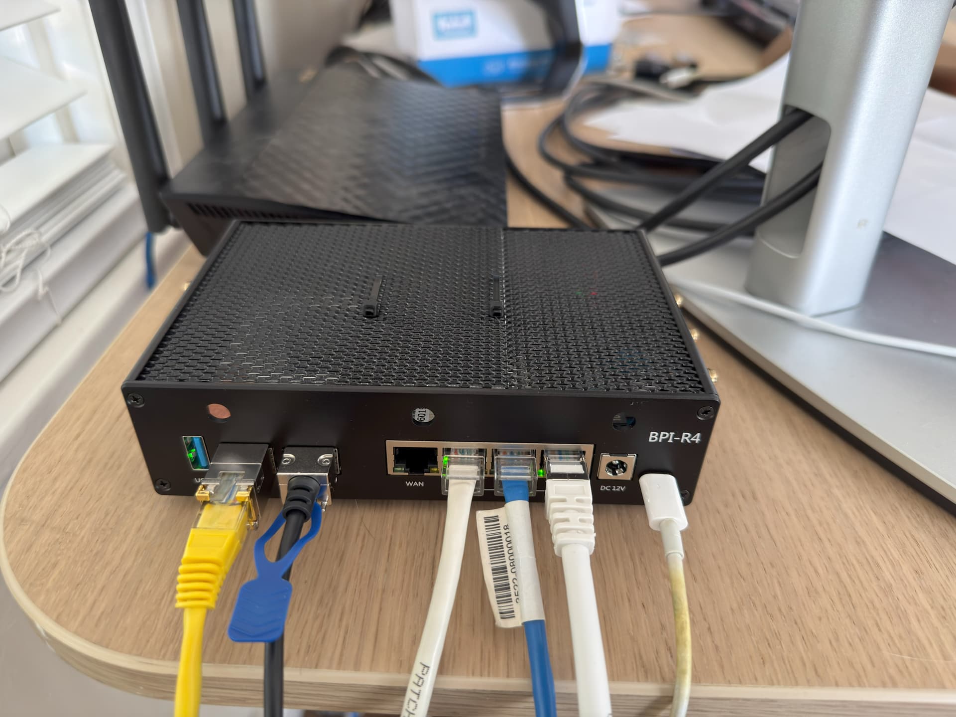
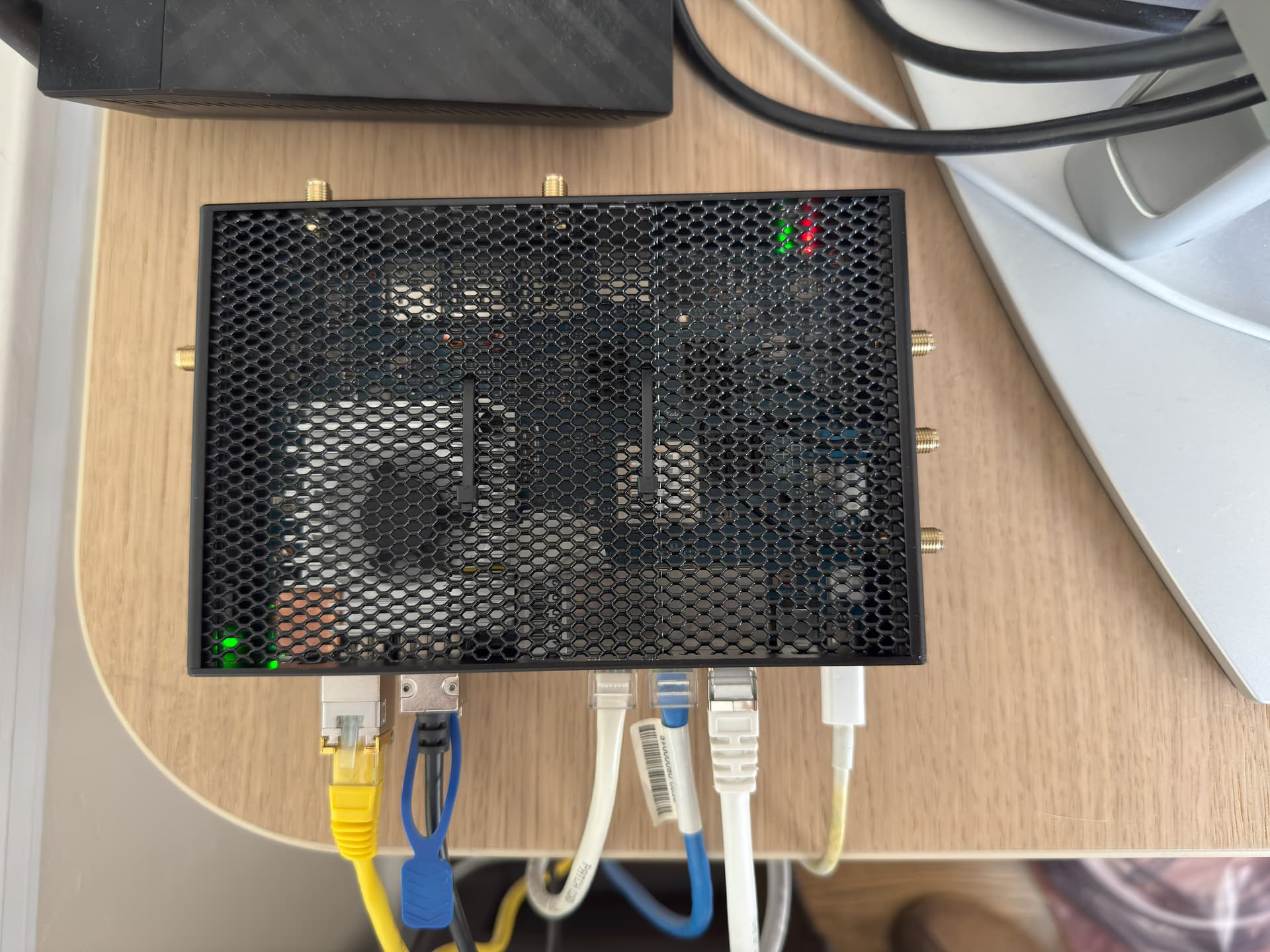
And of course, as everyone in this thread has discovered independently, the stock case lid had to go. I replaced it with a couple of 4" square car grill meshes tied together with a couple of zip ties (I couldn’t find a 4"x6" mesh, and didn’t bother cutting a larger mesh myself).
Current Temperatures (sfp1 is a BPI SFP-10G-T ethernet module in the WAN SFP port; DAC cable in the LAN SFP port)
# sensors
sfp1-isa-0000
Adapter: ISA adapter
VCC:           3.24 V  (crit min =  +3.00 V, min =  +3.10 V)
                       (max =  +3.50 V, crit max =  +3.60 V)
temperature:  +49.5°C  (low  = -45.0°C, high = +90.0°C)
                       (crit low = -50.0°C, crit = +95.0°C)
TX_power:    500.00 uW (max =   1.58 mW, min = 178.00 uW)
                       (lcrit = 158.00 uW, crit =   1.99 mW)
RX_power:    400.00 uW (max = 1000.00 uW, min =  22.00 uW)
                       (lcrit =  20.00 uW, crit =   1.12 mW)
bias:          6.00 mA (crit min =  +0.00 A, min =  +0.00 A)
                       (max =  +0.01 A, crit max =  +0.01 A)

cpu_thermal-virtual-0
Adapter: Virtual device
temp1:        +60.6°C

i2csfp111-mdio-0
Adapter: MDIO adapter
temp1:        +70.4°C  (low  = +10.0°C, high = +60.0°C)  ALARM (HIGH, CRIT)
                       (crit low =  +0.0°C, crit = +70.0°C)
The fan is on low as it’s triggered by the CPU temperature by default. I can reduce the MDIO adapter temperature by about 4C by setting the fan to high, but it’s not worth the extra decibels.
wanted a windtunnel case but prints with all the sides flat. so they’re stronger and printfaster, and faceplates matching the dimensions of the official case, to have option of reusing them instead. antenna’s are a little close together, but was testing it. step2 was gonna be to throw a bunch into the roof, or flip the assembly upside down and put them in that emptyspot. wanted to steal having the ftdi programmer port. but all mine are male usbA and didnt want to order a new one just for it, so didn’t model anything for it ![]()
2 Likes
hi can you share your case files?
added variants with the antennas moved around
2 Likes