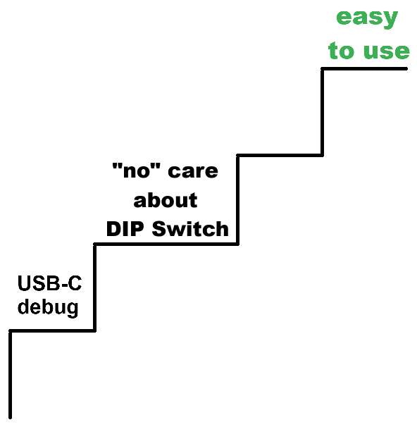
Introducing the USB-C debug port increased usability!
In the past years, we often had people who encountered problems with the use of DIP switches in general.
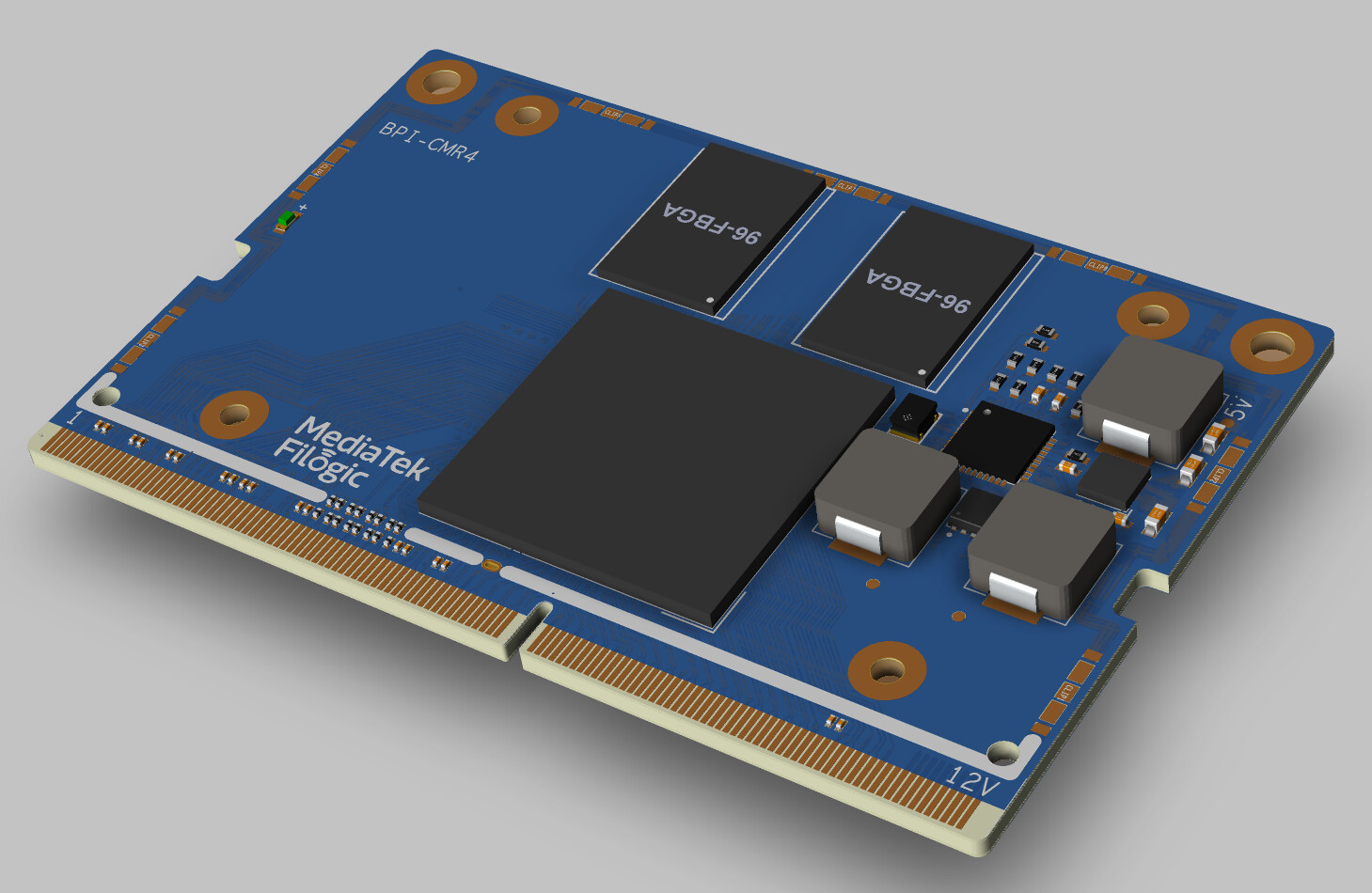
I didn’t want to question the use of NAND and eMMC.
But I was thinking about how we can make this more usable:
I’m not sure that a layman in their first days would be interested in boot topics so much! They are glad that the system works!
Maybe there will be people who never overcome this hurdle?
I’m not really sure how we can solve this without impeding advanced users. But solving the DIP switch topic will cause less frustrated people.
Because some people use these routers as their daily drivers. And changing the boot configuration mistakenly (by mechanical action) could cause time-consuming debugging. And this is not good on a day when you really have something else to do and need internet access.
II. Many other users still want to directly onboard eMMC, so this design is not considered for the time being.
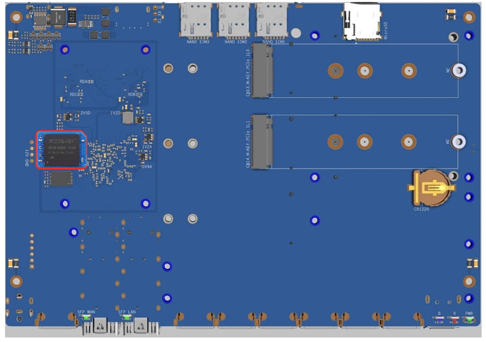
III. Also, many people will need 2~3 5G modules
IV.
Because it is a development board, we need to consider the different requirements of NAND/SD/eMMC boot, so we set a DIP switch.
We also noticed that BPI-R4 is prone to accidental touch, so the switch of R4Pro will be moved a little bit inside the board, and a component that requires more force to switch is used.
And we will suggest to MTK that the ROM Code of the next chip can be set to have a priority boot mode instead of bootStrap, such as SD>NOR>NAND>eMMC
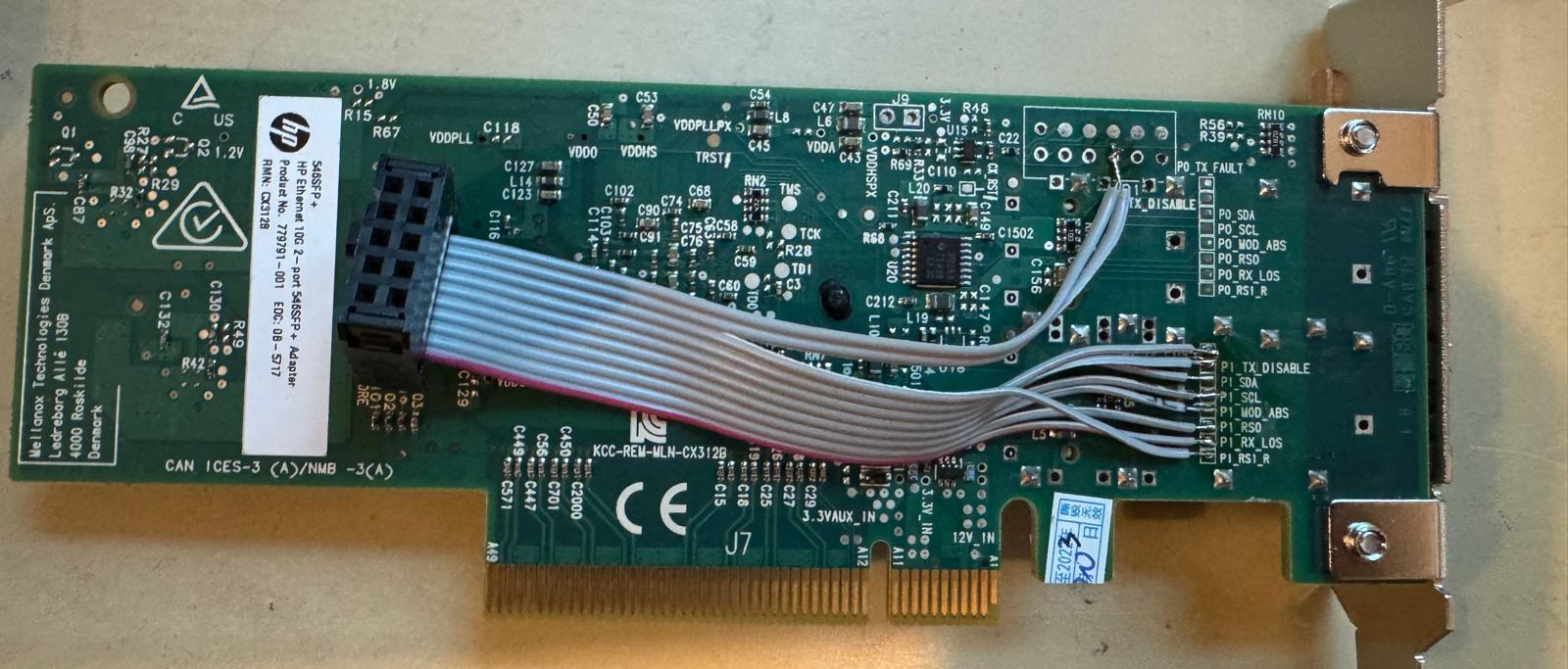
Could you put capacitor and power filters on the 5v and 12v lines, we suspect that due to the lack of power filters and caps on the BPI-R4 it causes higher noise therefore reducing signal strength, if you could add that it would solve the problem
(1) Please remove the SFP+ power mosfets (leaving the power permanently on), or attach them to a separate GPIO pin so that it is not connected to SFP moddef. The current BPI-R4 design is causing issues with several GPON ONU modules that requires hardware changes, documented here:
(2) Please consider adding pads (and maybe accompanying silkscreen) to the SFP+ control signals to make troubleshooting easier. There should be some space under the SFP cage which can be used for that.
Are there electrical issues (e.g. reduced speed due to weaker contact points) with the socket way? It would make upgrade more easy.
Really?..imho 1 would be enough
This will be a great change! Bit how to determine boot from emmc if nand/nor is also flashed with valid bootrom? I would take emmc as second to have system there (because of space) and leaving nand/nor as recovery when emmc is broken.
Another great change would be having 2.5g ports on the internal switch to not leave them unused like here and keep the dual-sfp without external switch.
Also adding poe to internal phys would be better that change one sfp to phy only for adding poe.
Thank you for opening the floor for BPI members to share their comments …
Consider these comments based on my experience with BPI-R4
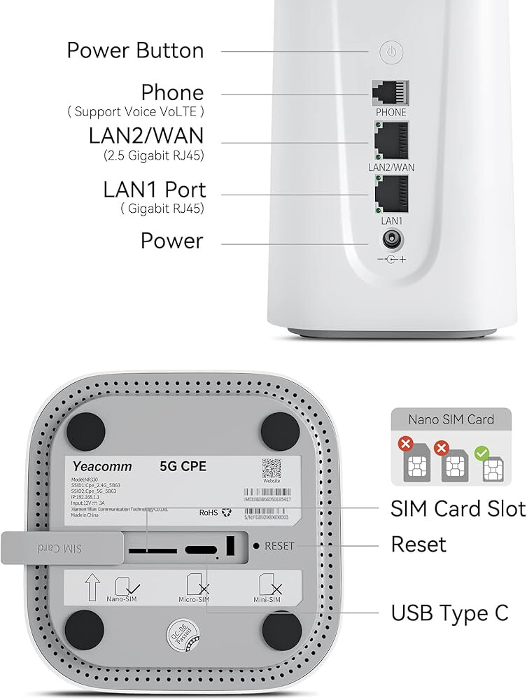
The overheating 5G modem due to lack of ventilation inside the case … Most of users that who using BPI-R4 as 5G Router facing this issue … most of time it will reach up to 74C … with Heatsink will reach up to 67C … With heatsink and without top cover Temp dropped to 43C To 51C
My point here (the aluminum case design is bad ) where its mentioned previously by BPI this case will absorb the heat but actually its not that much …
you can find many case like this
lets back to this point where
To be honest I don’t see any benefit from adding another two slot for 5G modems ,
Can you combine the speeds of the first 5G modem with the second modem, each having a separate
SIM card? If not, then what is the benefit of placing 3 or 5 modems on the board?
Last but not least
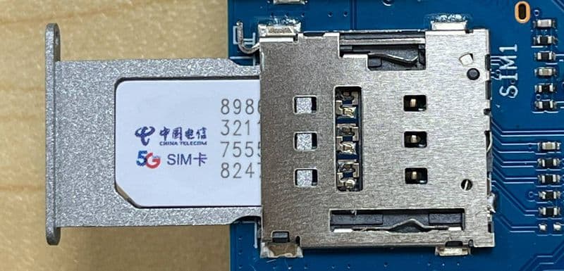
The SIM House (Tray) , I know some people they entered the SIM tray on opposite side on SIM SLOT 1 where its damaged and no use from the board as 5G Router without SIM Slot 1 because it linked to 5G modem and SIM slots 2&3 are not
My point here : the design of sim slot should be changed (Putting the sim on tray its contain a high of risk to damage the board due to not focusing . it should be replaced with pushing type ( Like Huaweii , ZTE, Nokia ,and etc… all other companies) using this type
actually many manufactures are more and more interested in poe routers (or “AIO” device). TP_Link ER7212PC, Unifi UDM SE, Mikrotik RB5009Upr… If we can have an openwrt poe AIO device it would be a killer. it would be great for the small-medium business market.
Vias, sockets, and socket instability, etc., each additional item will increase the overall risk.
In general, there is no big problem with using sockets. The cost increase caused by adding sockets is not the key, but the defect rate will be slightly higher than that of direct onboard, which is not something that enterprise users who deploy in large quantities would like to see.
Generally, one 5G Module is enough for an individual, but some companies may use two. In China, many people/companies may use three.
These are just some of my personal thoughts. I will suggest MTK later, but it depends on whether they will accept it.
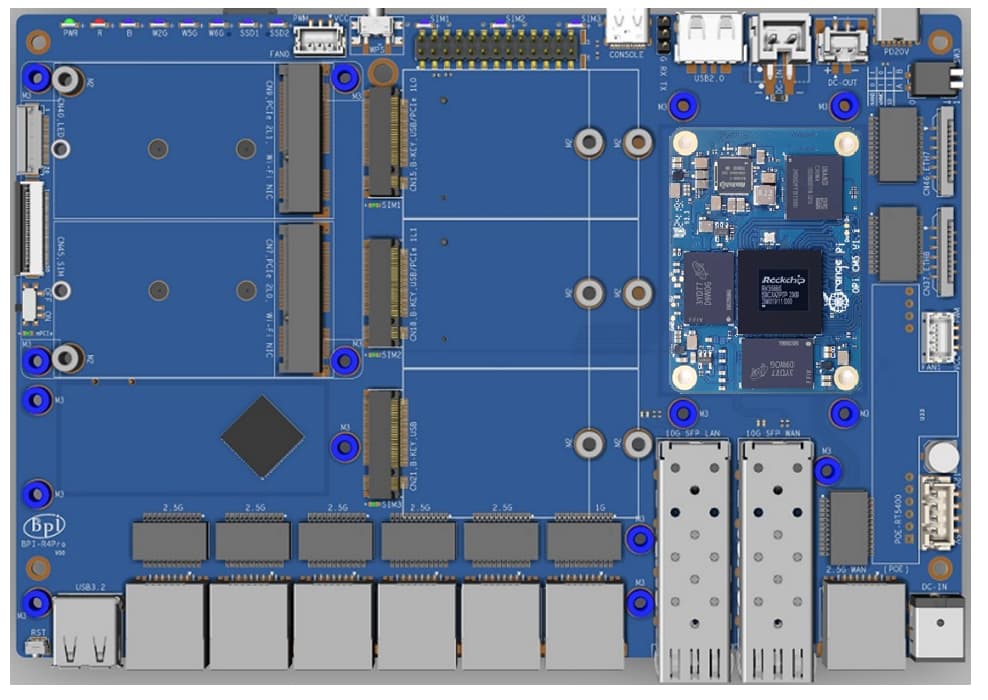
The latest schematic diagram adds two 10g phys, which are combo with SFP+.
Both internal phys(2.5G WAN) and 10G SFP will be layout at the same time, and switching can be achieved by simply changing DTS in software, without changing hardware
no wifi and 5G power consumption is not very high, so the goal is to make it as light and thin as possible, within 200x140mm;
The second one uses wifi/5G, which consumes a lot of power, so the size will be increased, and there may also be a place on the top of the case to install a 12CM standard computer fan.The noise is not too loud and easy to find a replacement.
As for the 5G module part, each module corresponds to a SIM card (it has been replaced with the R3mini’s SIM slot without card tray), which are independent of each other and can do Link Aggregation, But this is not a common scenario for individuals
I think the r4Pro could be slightly larger to directly expose all Ethernet ports without relying on FPC cables for extension. By integrating all ports, the board would lengthen enough to accommodate the BE19 component securely, avoiding a floating/unstable design. For users preferring a compact size, the r3mini remains a sufficiently small option. The r4Pro’s positioning should focus on addressing the shortcomings of the r4 while enhancing expandability. As for PoE support, this should be handled by dedicated PoE switches—the RT5400PoE’s power output cannot reliably support 48W, making its inclusion here less practical.
I hope if there is better way to access tom EMMC directly
And 1 sim card
And debian11 image for emmc with all necessary patch to make sim data connection work
@sinovoip@sinovoip1, I can see you are planning to release the new version with 2.5G RJ45 ports. Does it mean you have solved the issue with non-working 2.5G on the original BPI-R4 ? If so, are you planning to publish what was wrong, what and how it got fixed ?
There are still people out there with half-bricked (well, technically speaking partially unusable) R4s and it would be really shame if you released a successor with the same flaw