Instead of connecting all 2.4 GHz antennas on one side and all 5 GHz antennas on the other side you will get better results if you interleave them and thereby maximizing the distance between antennas which are used for the same band. 2~3 cm between two antennas of the same band will not allow for good results with MiMo, the more distance between them, the better…
I thought about that too but could not find any source testing this theory out. However, since MU-MIMO requires multiple antennas, pointing two in one and the other two in the opposite direction might not be favorable. Since this is going off topic, I guess creating a new post would be good.
Edit: There we go
Thanks Mike!
In reply to your questions:
-
- My design started of from one I found on thingiverse that used slits on the side. I ended up designing it from scratch but kept that “slit” feature. So no real special reason. The honeycomb pattern would work just as well.
-
- I bought some cheap 40mm x 10mm 5v fans on amazon. I know there are 6 and 8mm versions but I wasn’t able to find any for sale. The 10mm one works well even with the heatsinks I used ( also bought from amazon, I ordered one of those boxes that have alot of them in different shapes and sizes ).
-
- no idea really, I print using the printer I have at the office. The only thing I would recommend would be using a material that is heat resistant, like ABS or PC or Nylon with carbon fibers.
-
- regarding the STL files, Have you tried copying the project I made on thinkercad and edit it yourself, instead of importing the stl files to whatever software you are using? this is the link: https://www.tinkercad.com/things/fqroXeQOz7a-banana-pi-rpi-3-case
-
- regarding adding a second fan, I added a taller version of the case that may allow for it. So there are basically two sized versions.
-
- I would be glad to print a case and send it to you. Currently the printer is printing stuff non stop that I need for some projects we are working on ( nothing related really, it’s printing some case parts for a visual AI sensor we are making ), but when this stops, probably next week, I will have print time to print a case for you if you want.
1 Like
You are most welcome and thanks for your comprehensive feedback! If my local 3D-Print-Service I found can’t help, I’d gladly accept you offer printing me a case … all expenses + tip will be covered 
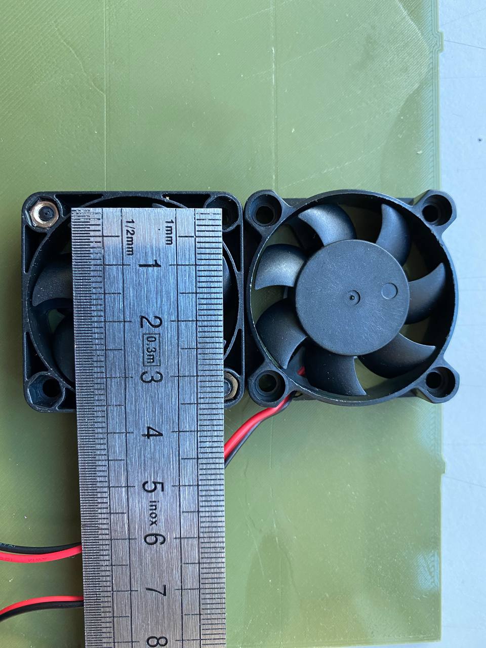
Does your 40mm fan by any chance have the same dimension as my nf-a4x10-5v-pwm:
- Mounting holes 33mm apart
- 37mm diameter intake
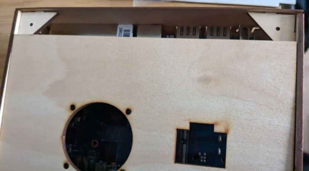
I place the cutout in the top case slightly off center (both 49mm form left and bottom) to the main CPU to cool the WiFi chips. The 4G Antennae, so the cables take the same space as those from the Wifi antennae, are placed:
- 9mm respectively 29mm (centered above the SIM from the left
- 16mm from the top
Just for reference in case any measure makes more sense to you compared to the current placement.
Cheers Mike
So I have two different fans ( in terms of physical aspect ), but they both have the same 33mm between mounting holes and 38mm diameter intake.
1 Like
Hey awesome work! But is the project still on tinkercard? I tried to follow the link but got an error
yep:
I missed sharing the promised 3D-Files. It is not fully production ready but is coming quite close. See my additions at the bottom.
All files provided in courtesy of Simon from 3D-Druck in Bensheim (no add, he’s a really nice guy!)
As follows the files with their respective modifications.
Case
- Intake (hexagonal)
- Quick access for m.2 Slot
- Antenna mounting holes with flush site to prevent rotation upon tighten them

BPI-R3 Case 3D-Model.rar (662.6 KB)
Cover for SSD - Not available in metal case from sinovoip!
- Intake for passive ventilation
- Screw hole adjustments for flushed finished

BPI-R3 Cover Bottom 3D-Model.rar (125.0 KB)
Top Cover
- LED-Carrier Light mounting
- 4G/5G antenna mounting holes
- Intake for Noctua NF-A4x10 5V PWM Note: It is not confirmed if that fan works. As of today, some changes are in progress see link at the bottom with the comment from @frank-w

BPI-R3 Cover Top 3D-Model.rar (366.5 KB)
Final notes. There are a few modifications I, two them absolutely required, that are worth adding:
- Required - Wall thickness: In order to gain sufficient thread to mount the antenna, either add a cavity to fit the 8mm hex nut (basically flush mount) or simply decrease the wall thickness.
- Required - Reset buttons: Fine tune size to 4mm diameter and location of reset buttons
- Optional - Antenna holes in the top case: Align size and form to those Wifi-Antenna mounts of the main case
- Optional - Flush mount screws of the fan in the top case
- Optional - Jumper hole is quite tight
Thanks for working on this too
You can decrease the wall thickness and move screws onto extra areas (i guess these are the cause for wall thickness) and make wall same height as front for better alignment.
So from top view (front up):
_________
|•/   \•|
My not yet ready case:
That is quite a great idea relocating the top lid screws to attenuate the wall thickness. I believe a combination of both is favorable considering the longevity, i.e. when the threading get damaged, of the case.
I’d not make the walls too thin as, depending on the used filament, the mounting pressure and applied forces, i.e. when you accidentally bend a wifi antenna, could cause some structural damage. Using the 8 mm wrench was a bit annoying / wiggly but I am uncertain if, by flush mounting them, the filament can withstand the forces when tightening the antenna screws.
Maybe both are not necessary when the top lid designed to slide into the case entirely and only two screws, like in the metal case, are used for fastening on the bottom of the main case which should be sturdy enough.
This is my case, I 3D scanned the upper glove box in my Prius and not the R3 load balances three LTE modems ![]() its battery powered now and the push button, well… its a push button. I need to add a few more fans though, the board been getting hot even with the little pwm fan.
its battery powered now and the push button, well… its a push button. I need to add a few more fans though, the board been getting hot even with the little pwm fan.
anyone have a bright idea on the type of plastic i can use to route the lights on the board to this front area?

I created my own version of a case for the Banana PI BPI-R3, designed specifically for 3D printing without supports. All parts are optimized for easy printing with minimal extra material.
The front panel has snap locks for secure assembly, and only four screws are needed to mount the board plus four more for the top cover. Inside, there is a slot for a USB-C trigger, allowing you to power the BPI-R3 from a regular USB power adapter.
The case has mounting holes for wall installation. They match the mounting points of the original metal case, so if you used the stock bracket before, it will fit this version too.
I don’t use the Reset and WPS buttons, so I didn’t add holes for them, nor for status LEDs.
There are dedicated antenna slots: two antennas mount on the sides and four on the rear panel. The design secures the inner nut, so you don’t need two wrenches to install the antennas.
The top cover has an opening for a Noctua NF-A6x15 fan (60×60×15 mm, 5V PWM). If needed, you can modify the cover for other fans or use a perforated version for passive cooling.