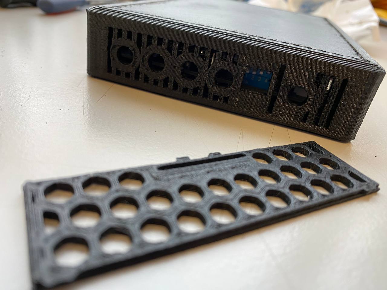
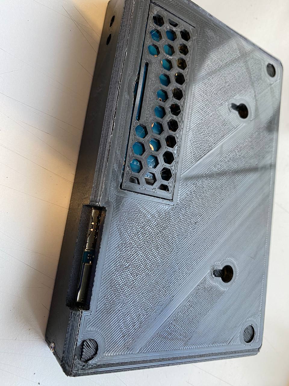
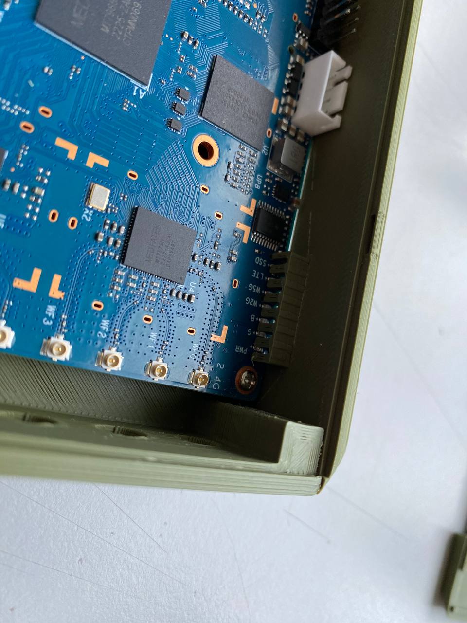
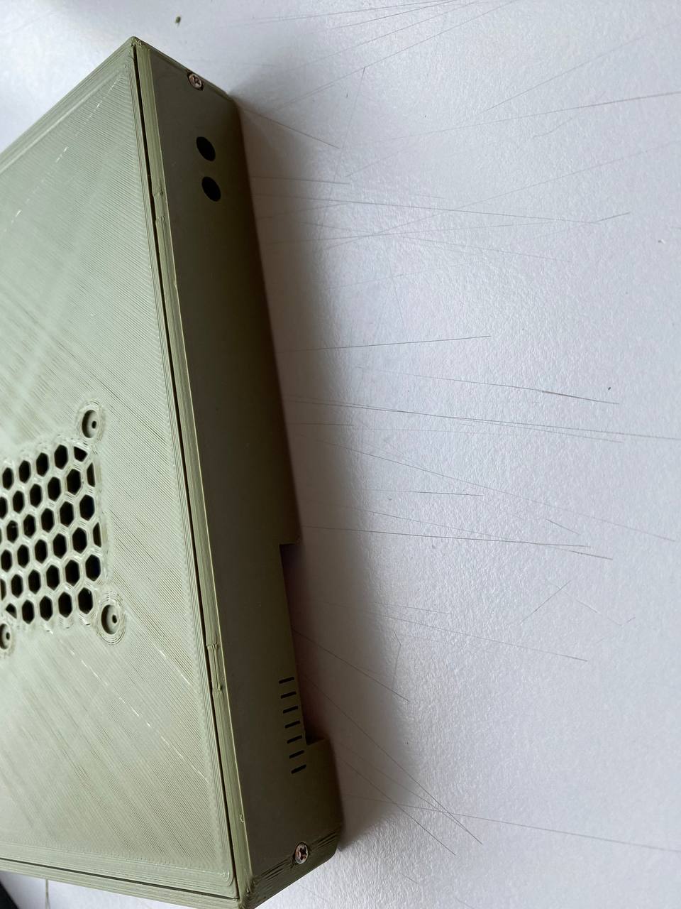
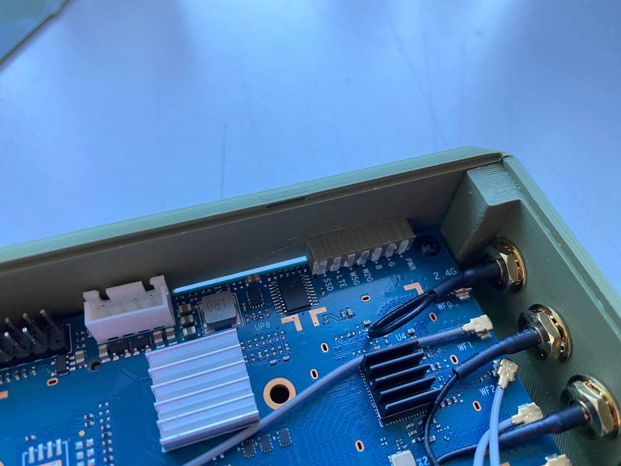
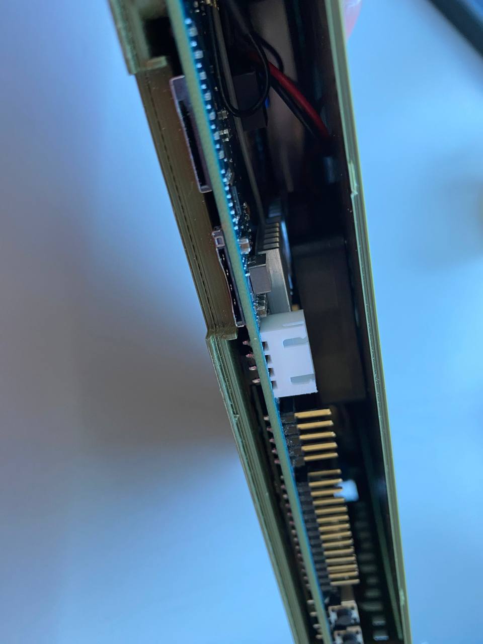
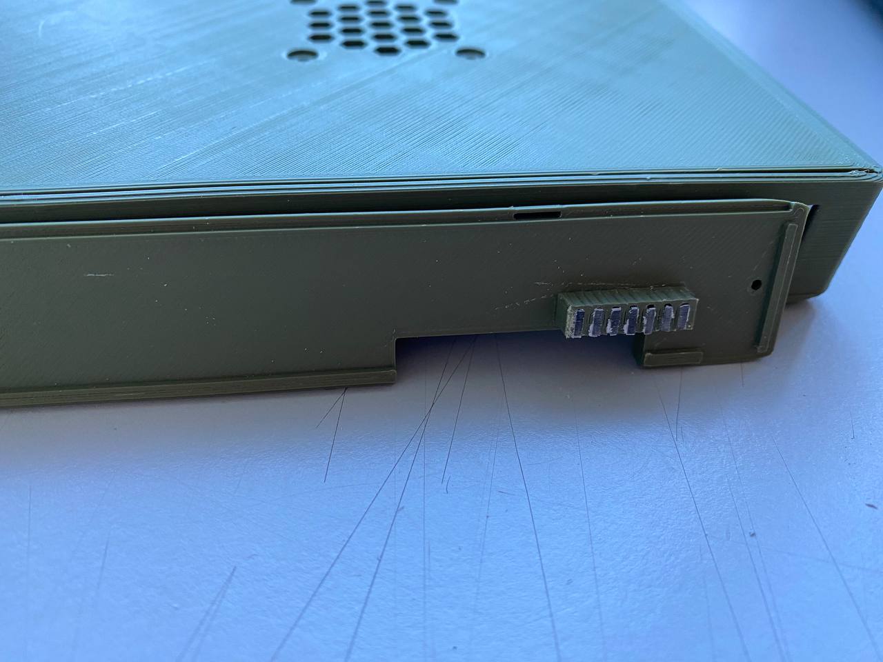
Looks good so far,is it possible to easy access bootswitches from outside? Looks like there is too much space for it…maybe left wall can be closer to the board (maybe only around the bootswitches)?
The boot switch is easy set with the tip of a pen. Shortening the space would make the antennas impossible to mount.
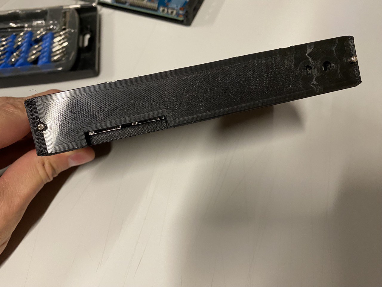
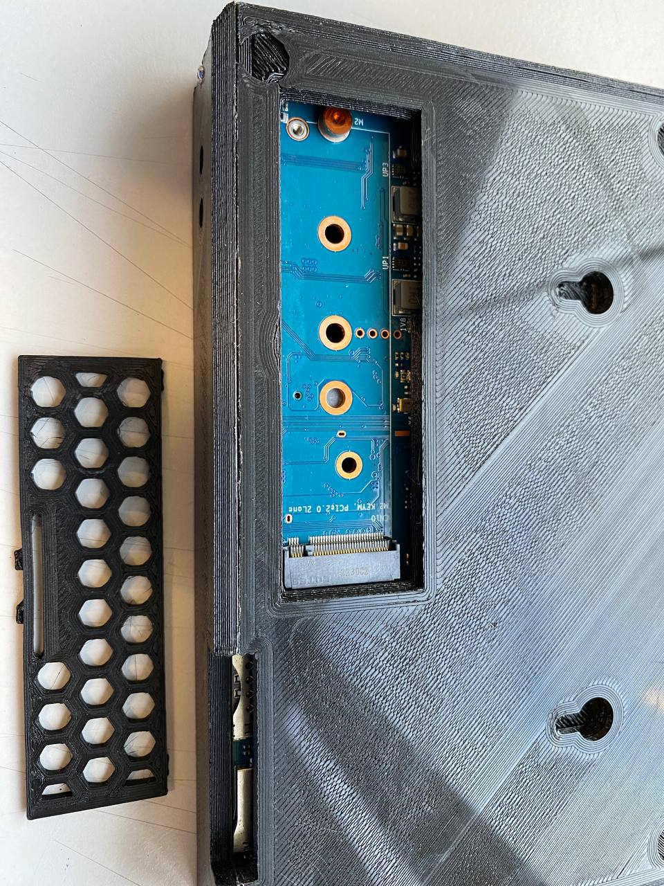
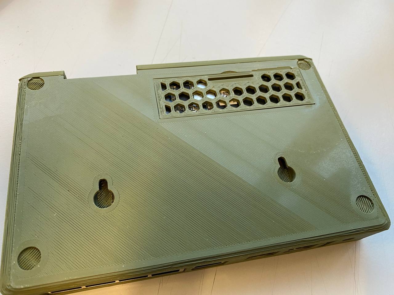
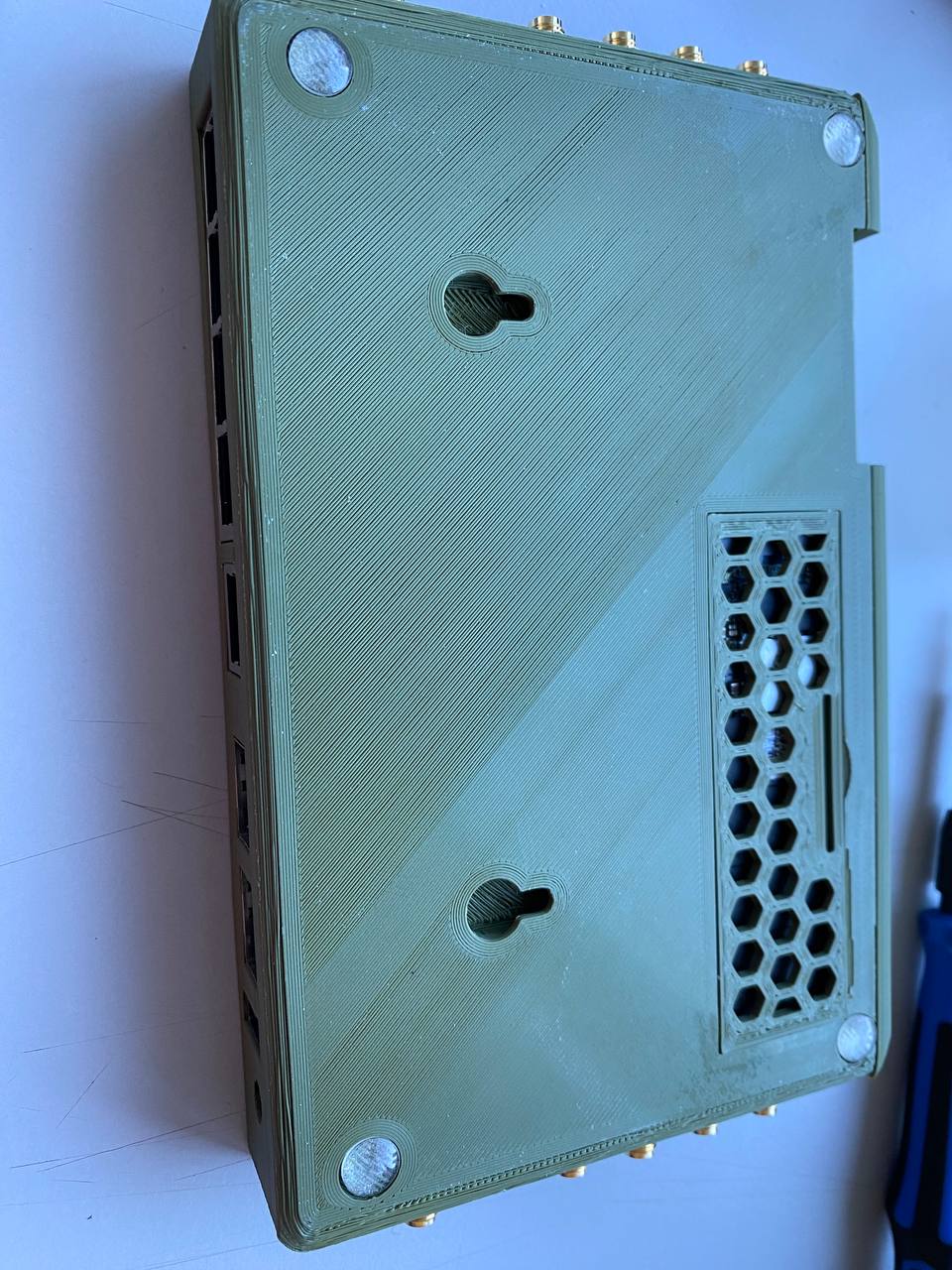
I was able to do a removable nvme cover that works really well.
I think by the end of this week I will have something that can be published.
I just need to finish the top cover and do some slight tweak to the way the back panel the the main case mate.
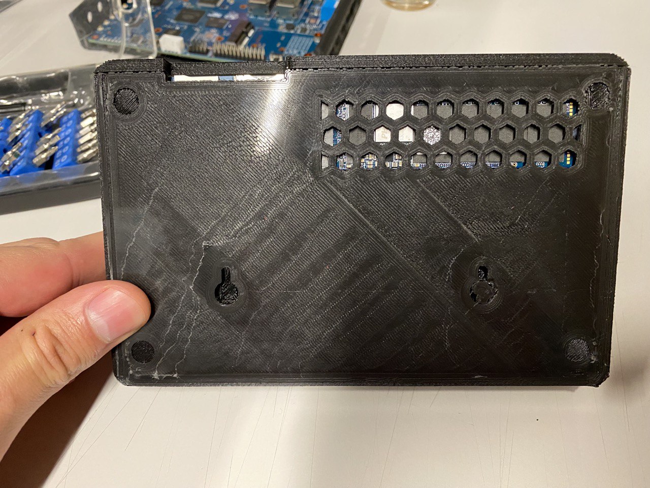
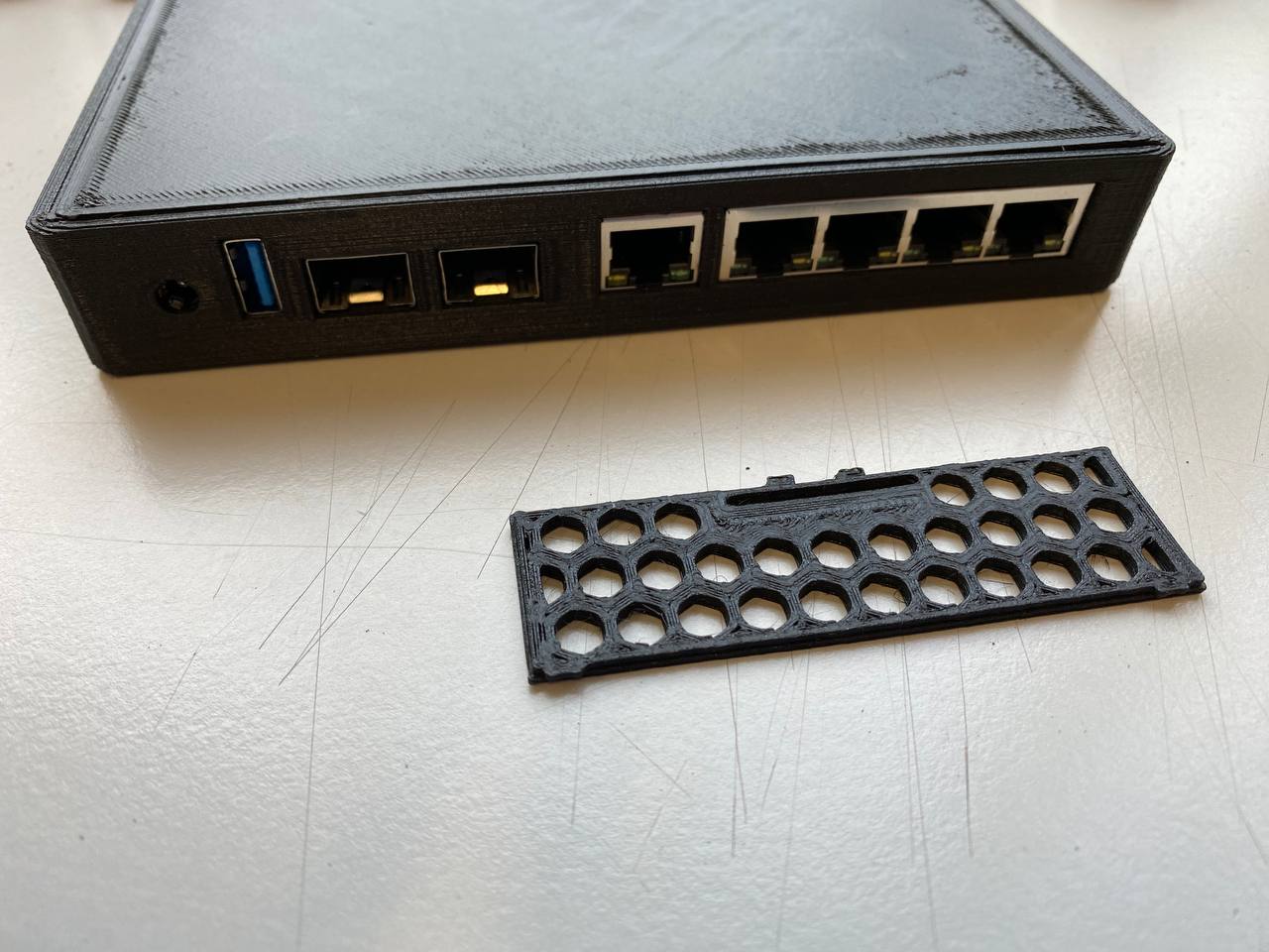
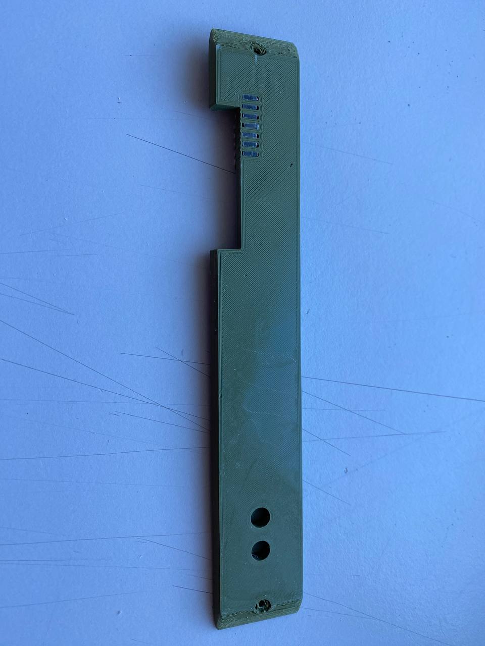
Looks very good so far, are leds visible outside (looks like you made dark walls between then to have no disturbing light) a bracket for gpio and maybe for debug-uart. Please make sure board lays on bottom part below gpio pins to not bend down on connection.
yes, the leds are visible from the outside but the idea is to also print some transparent plastic rectangles to bring the light from the led to the back. I am just fine tunning the spacing of that part as it is not perfect yet. I have some transparent filament and will then try the plastic rectangles.
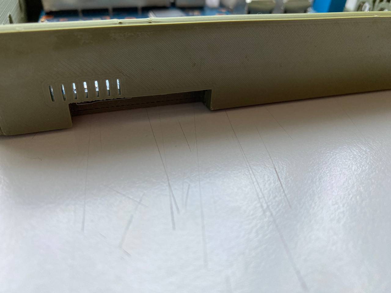
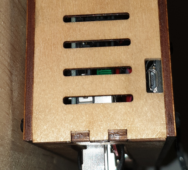
the debug-uart one can place the cables and get them out from any of the side vents. doesn’t look neat but I haven’t seen any uart female connector that can be placed there so I think like this is fine. no need for another hole.
Regarding the gpio, I am struggling with the idea of adding a hole+cover for it. The thing is, this is a case for router purposes and I can’t find a use case for the gpios on a router setup.
I for sure will not use a case with a gpio hole in it but I can add one for you if you think it is worth it.
Maybe for gpio it is enough to lower the back wall to have small gap between it and the top cover. So this is not Critical as long as top cover can be removed and board does not bend on connection
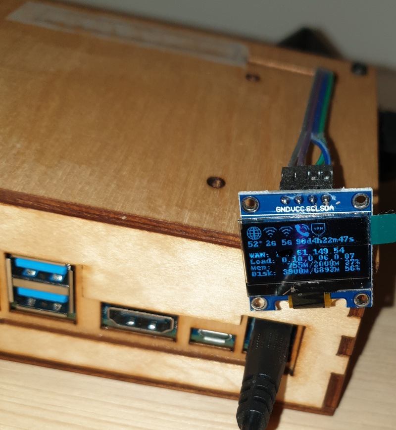
A possible use case is to add a display (like i did) or similar.
For uart i currently have a hole in left wall of my r2 case so possible to do same on r3 case,no problem…was only a thought.
For leds maybe a triangle (90° angle in corner of led and wall) is better for light transfer (reflexion on hypothenusis).
yes, the screw can be accessed. In your use case what makes sense is not the GPIO being available but actually designing a case that can have that amazing display somewhere on it.
Can you share the display link and also it’s measures, maybe I can try to fit it somewhere or make a case that can have it
Yes of course putting display into the case is better (was added later to my r2). It was not meant to create a specific case version,only for a possible usecase of gpio on router setup
It is a cheap 0.96 inch oled display which can be found on ebay,but you do not need add work to it
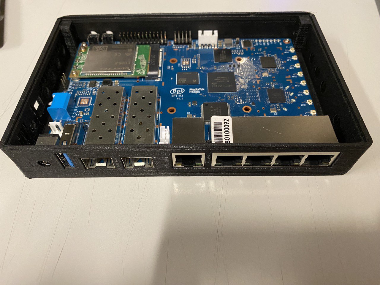
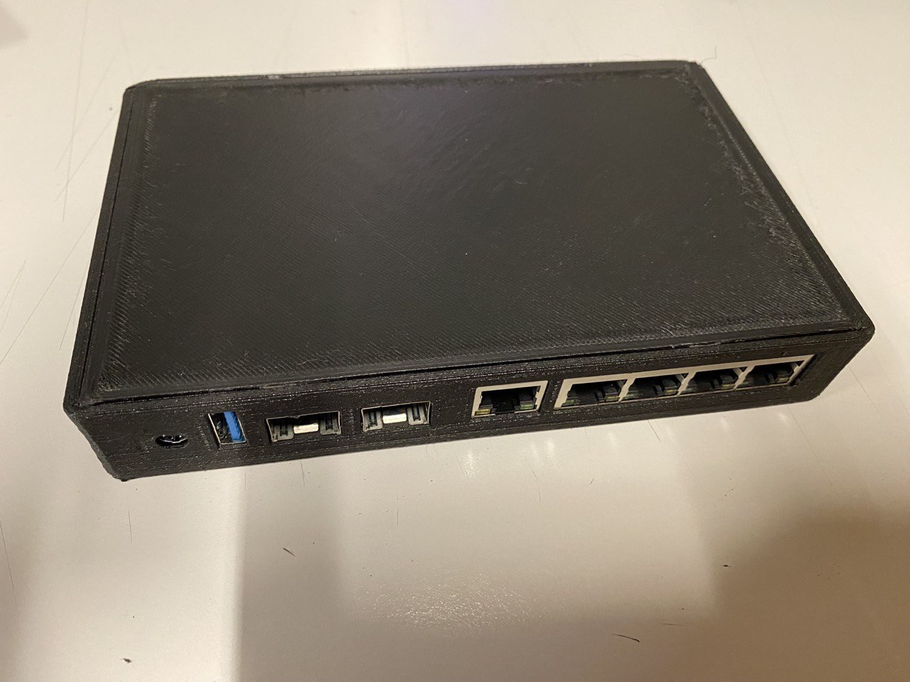
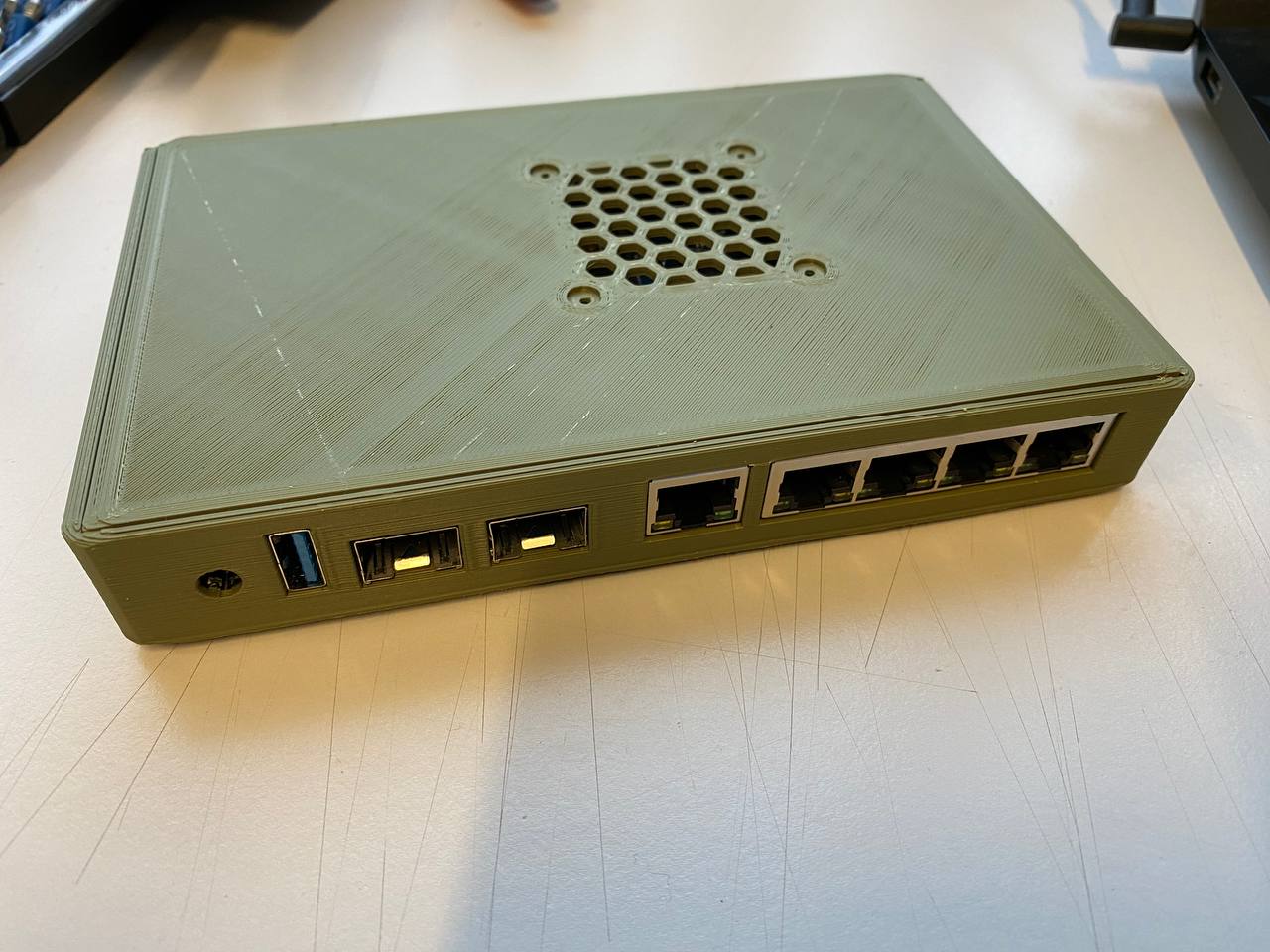
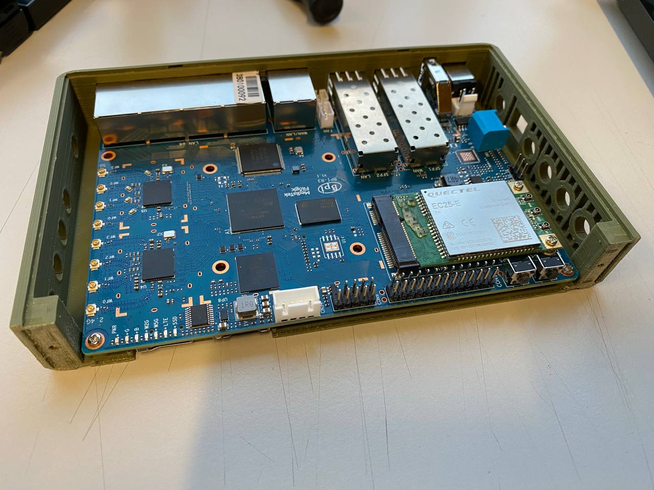
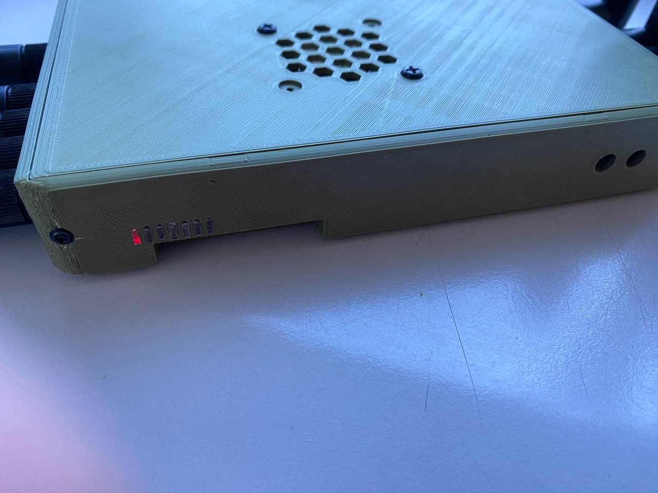
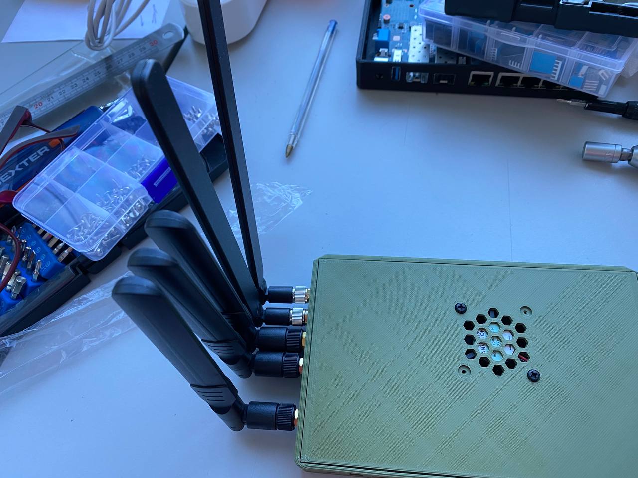
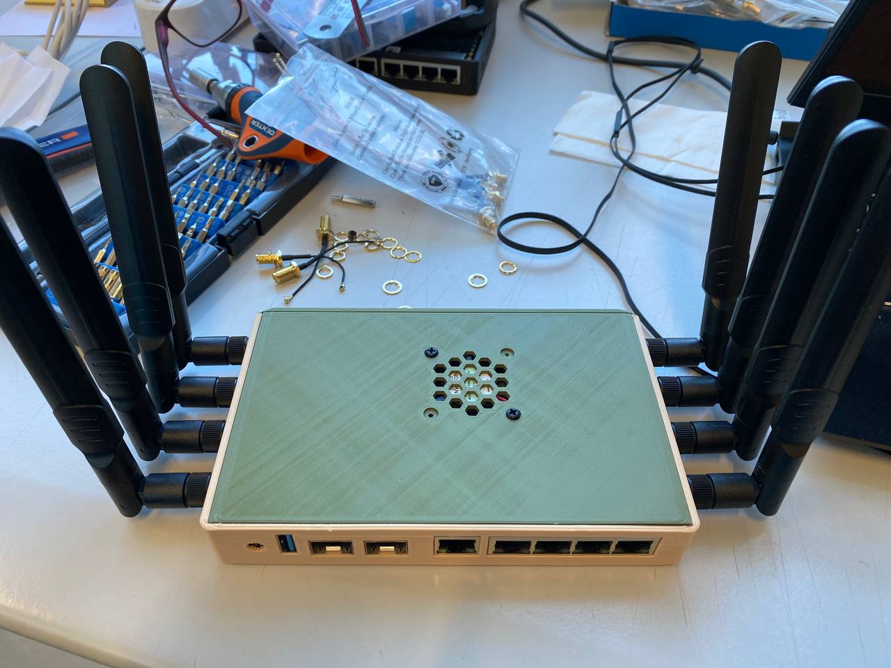
Well, nothing like doing a test fit to see what is wrong.
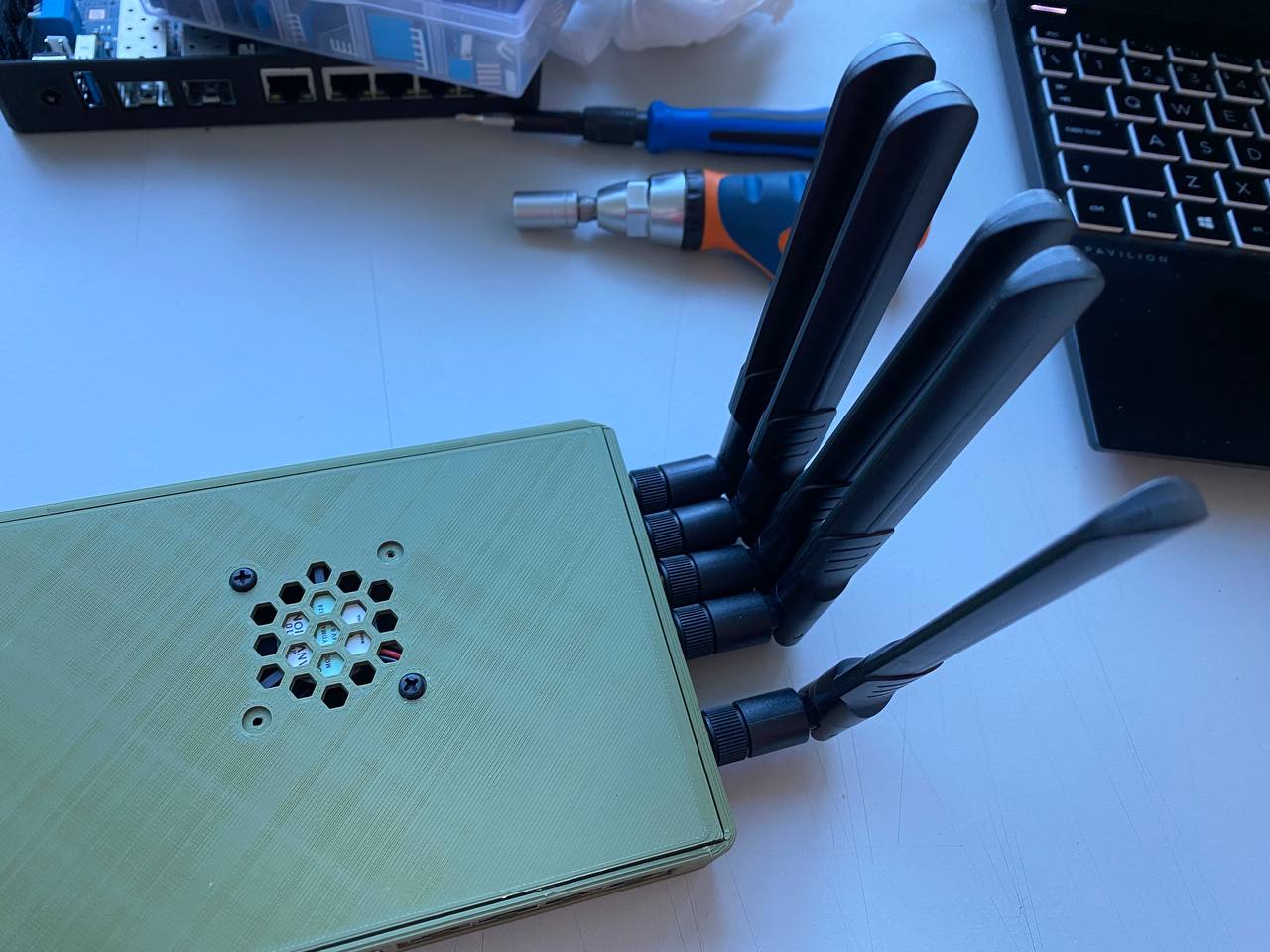
I will need to fix the spacing between the antennas as it’s too short. Apart from that it’s really good.
The leds work quite well. I made and printed some transparent plastic strips and the light from the leds propagates nicely to the back.
the fan also fits and clears the ships with heatsinks on them. this is a 40mm fan with 10mm height but there are some 40mm fans with 6-7mm height that will allow for taller heatsinks.
I think after fixing the antenna spacing it’s done. If there are any suggestions please let me know and I will see if I can add them to the case.
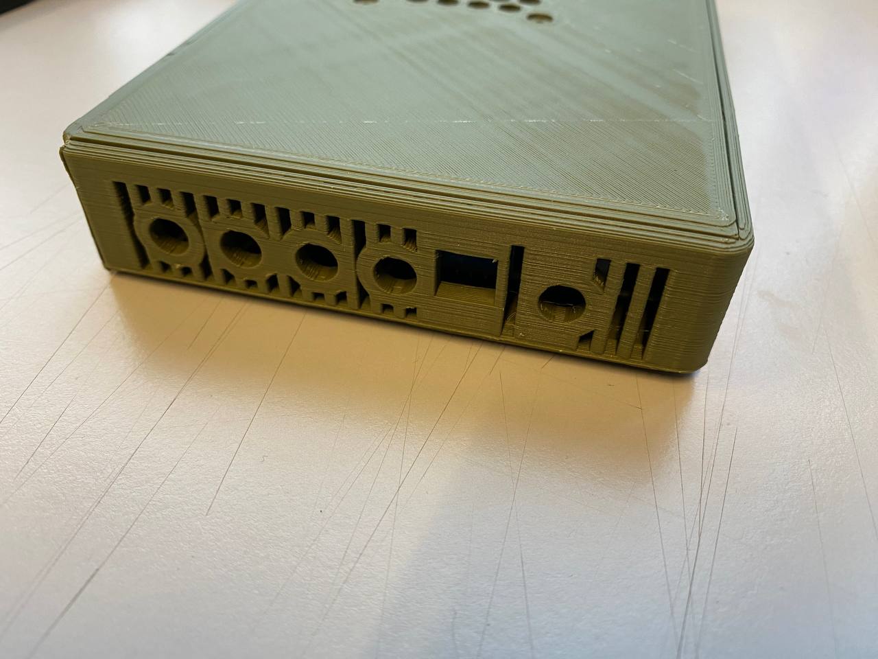
yes, wall mounting works but it will never allow for all the antennas to be in the vertical position no matter the amount of spacing one has. for this the antennas would need to be all in the back plate, and for this the case would need to be at least 1cm taller or 1.5cm longer. If I make it longer we lose easy access to the sim and sd card and also makes it harder for the leds. Making it taller is a possibility but I would prefer not to do it.
I’m printing a test version with the antennas spaced as much as the available space allows but I’m not sure it will work. if it doesn’t I don’t see any other option but to either make the case taller or move the two gsm antennas to the back. Moving the gsm antennas is not nice because it then makes it harder to assemble the case ( the antenna cables must be connected to the gsm module and one needs to take care not to disconnect them when positioning and screwing the screws.
Maybe additional antennas can be placed on back/top if needed. I use a flat lte antenna which does not need a hole in case
But yes,left wall is tricky as you need to leave space for boot-switches and maybe debug-uart connector. Top is also easy because of gpio,usb and sata power…mhm…and it should look symetrical from outside…not easy
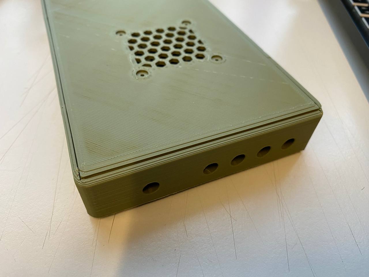
No way I could fit the 5 antennas on the sides so I will relocate the GSM antennas to the back plate. I will make two versions, the current one without the two GSM antennas on the backplate and another with two holes for the GSM antennas.
Will test fit today or tomorrow and then publish the files.
Thats ok,i think everybody who prints such a case can drill 2 or more holes if case design does not prevent it (by having air ventilation slots on possible places).
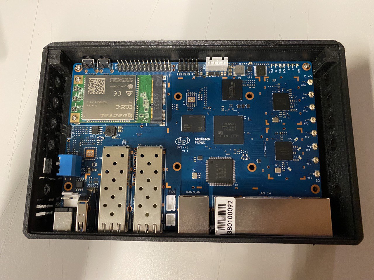
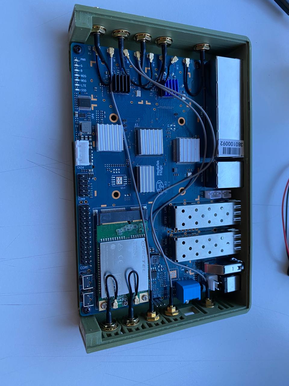
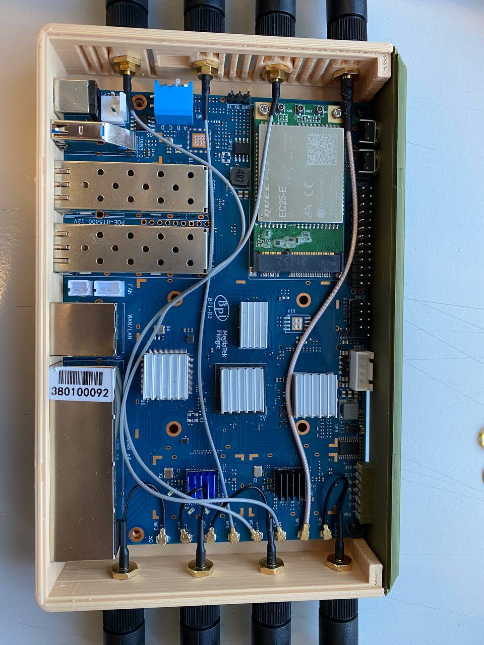
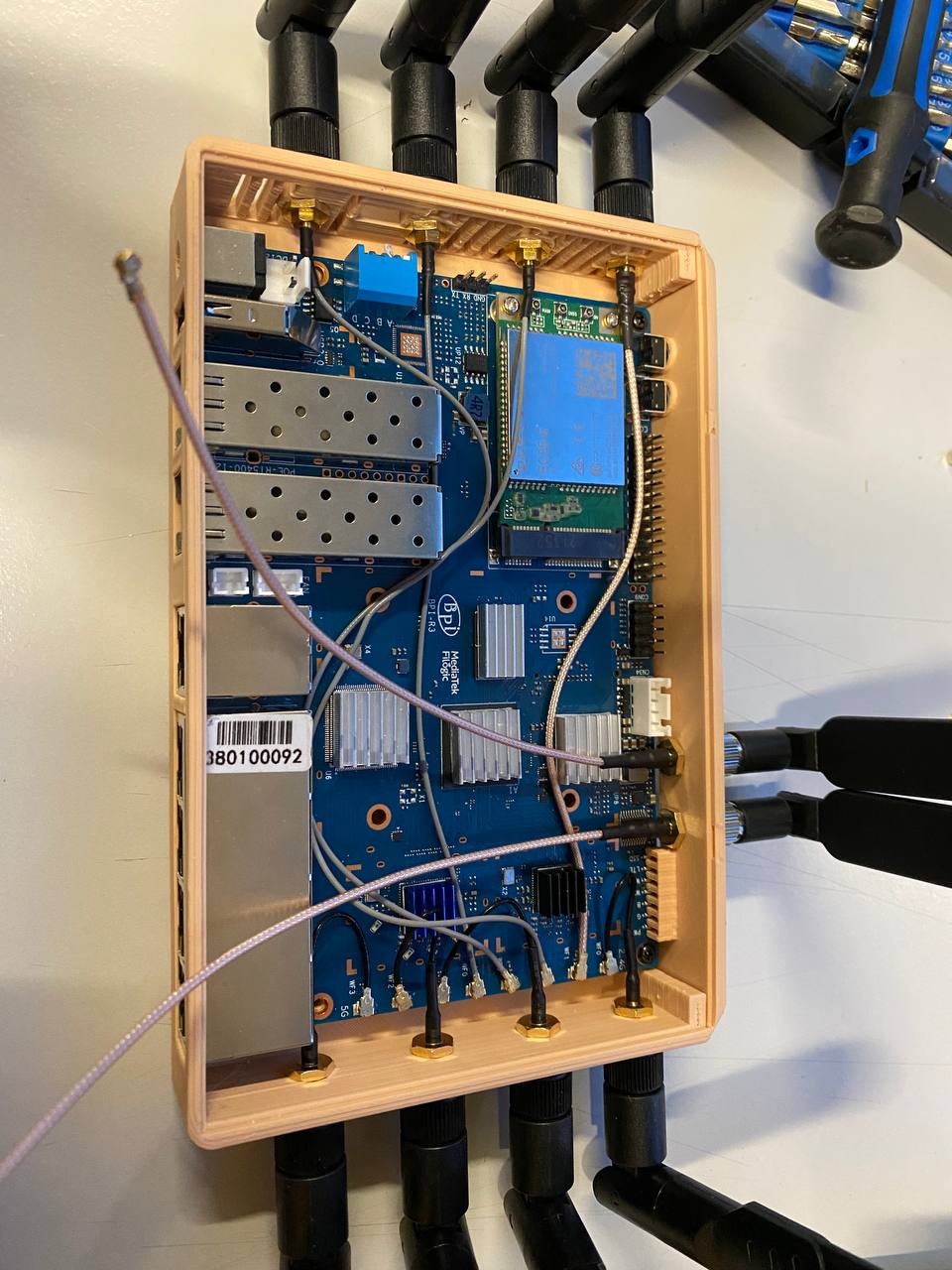
How does it look inside with these 8 antennas assembled and from left side?
It looks quite better. Before it was a bit hard to install the antennas in two places, now they don’t interfere anymore with any of the pins or other features of the board.

 can’t wait to try it