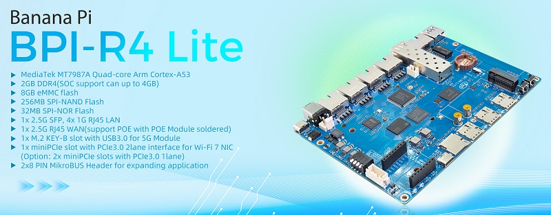
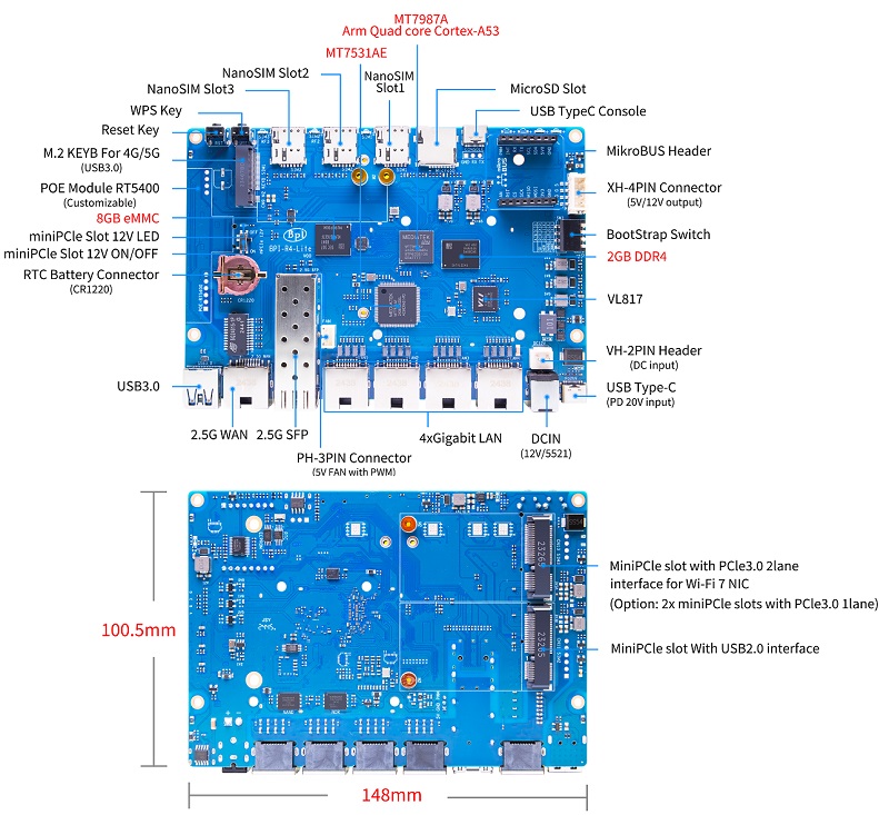
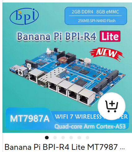
Banana Pi BPI-R4 Lite smart router board design with MediaTek MT7987A Quad-core Arm Cortex-A53,it support 2GB DDR4 and 8G eMMC Flash on board. 1 2.5G SFP and 1 2.5G RJ45 WAN , support 4 x 1G RJ45 LAN port. support M.2 for 4G/5G module.1x miniPCIe slot with PCIe3.0 2lane interface for Wi-Fi 7 NIC.
The MediaTek MT7987A is a world-leading network processing platform for high-performance and reliable networking experiences, both in wired and wireless applications. The MT7987A comprises a rich connection interface set, including 1 2.5 Gigabit Ethernet port, 2 HSGMII/SGMII interfaces, 1 PCIe 3.0 2L/1+1L interface, and 1 USB 3.2 Gen1 port and 1 USB 2.0 port, where the USB3 port shares the same interface with 1 HSGMII/SGMII interface; only one can be activated at a time. The MT7987A further enables seamless Wi-Fi 7 connectivity with its Wi-Fi 7 companion chip.
Key Features
MediaTek MT7987A Quad-core Arm Cortex-A53
2GB DDR4(SOC support can up to 4GB)
8GB eMMC flash
256MB SPI-NAND Flash
32MB SPI-NOR Flash
Micro SD card slot
1x 2.5G SFP
1x 2.5G RJ45 WAN(support POE with POE Module soldered)
4x 1G RJ45 LAN
1x USB3.0 slot
1x M.2 KEY-B slot with USB3.0 for 5G Module
1x miniPCIe slot with PCIe3.0 2lane interface for Wi-Fi 7 NIC (Option: 2x miniPCIe slots with PCIe3.0 1lane)
Is there a practical reason for the microbus instead of gpio-header? Have not found any modules for it on quick search and imho it takes more space compared to dualrow gpio header.
Edit: found schematic and there m.2 slot is only usb (3),so nvme will not work.
I wonder about the spi multiplexer for sdmmc+emmc…does mt7987 not have dedicated mmc controller?
There is a layout / assembly error on the (at least my) V1.1 PCB assembly. On the pictures it seems to be correct. Maybe a short check could be worth.
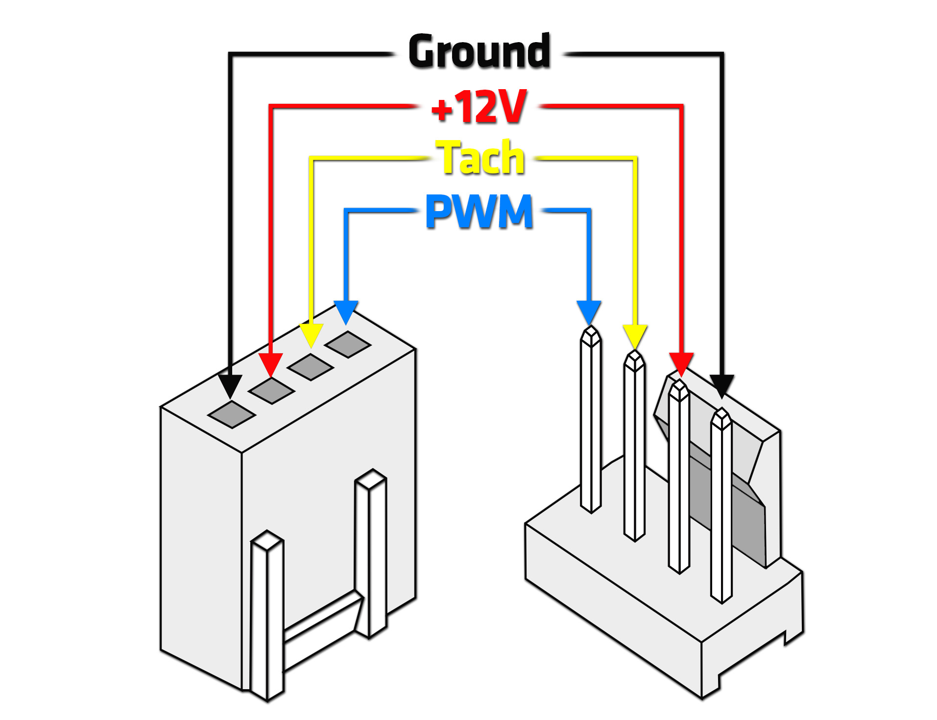
The KK 4-Pin header (I think a Molex 47054-1000) needs to be rotated for 180°. The “orientation pin” is on the side of ground. See in the picture. On my it is on the side of “PWM”
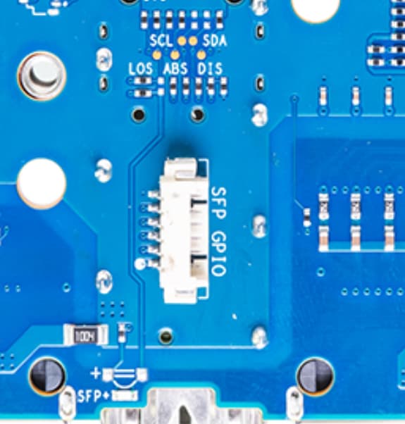
Which connector do you mean? I see only the 3pin 5v fan xonnector near SFP cage and the 4-pin xh connector next to bootstrap switch which seems no fan connector.
I think there are two designs (1.0 and 1.1?) of the PCB. In the picture above is eventually the old one. If you check the one on the website you will see a additional connector at the left corner.
I am considering buying this board (good deal on Amazon).
I hope forum members can help answering a couple of clarifications:
Looking at the pics above in this thread and the BPI-R4 Lite docs the board pics are inconsistent.
In the above pictures, the PCIe connectors are in the bottom of the board whereas in the docs they are on the top of the board. Even the YouTube clip shows the PCIe connectors on the top. All the AliExpress listings are also showing the connectors on the top (pic below)
If they are on the topside of the board, then how to install a fan or a passive heat sink without obstructing cards on the PCIe connectors?