Please refer to below script and then run commands source mt_gpio.sh
mt_gpio_mode 200 0
mt_gpio_dir 200 in
mt_gpio_value 200 | echo $?
mt_gpio.sh
SYS_FILE=/sys/devices/platform/1000b000.pinctrl/mt_gpio
mt_gpio_mode()
{
   pin=$1
   mode=$2

   if [ ! -f ${SYS_FILE} ]; then
       exit 1
   fi

   echo "mode $pin $mode" > ${SYS_FILE}

   return 0
}

mt_gpio_dir()
{
   pin=$1
   dir=$2

   if [ "x${dir}" == "xout" ]; then
       dir_val=1
   else
       dir_val=0
   fi

   if [ ! -f ${SYS_FILE} ]; then
       exit 1
   fi

   echo "dir $pin $dir_val" > ${SYS_FILE}

   return 0
}

mt_gpio_out()
{
   pin=$1
   out=$2

   if [ ! -f ${SYS_FILE} ]; then
       exit 1
   fi

   echo "out $pin $out" > ${SYS_FILE}

   return 0
}

mt_gpio_in()
{
   pin=$1

   if [ ! -f ${SYS_FILE} ]; then
       exit 1
   fi

   echo "start $1" > ${SYS_FILE}
   result=`cat ${SYS_FILE} | grep "$1"`

   if [ "x${result}" == "x" ]; then
       echo "can't get $pin status"
       exit 2
   fi
   echo ${result}
   pin_val=`echo ${result} | awk -F ' |-' '{print $5}'`
   if [ ${pin_val} == "0" ] ; then
       return 0
   else
       return 1
   fi

   return 0

}
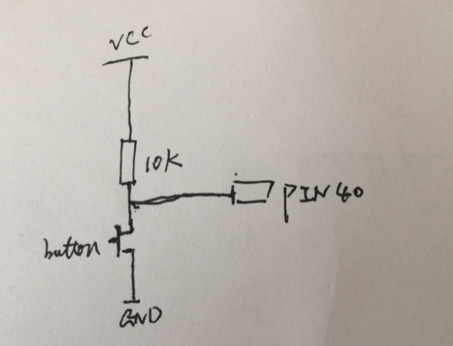
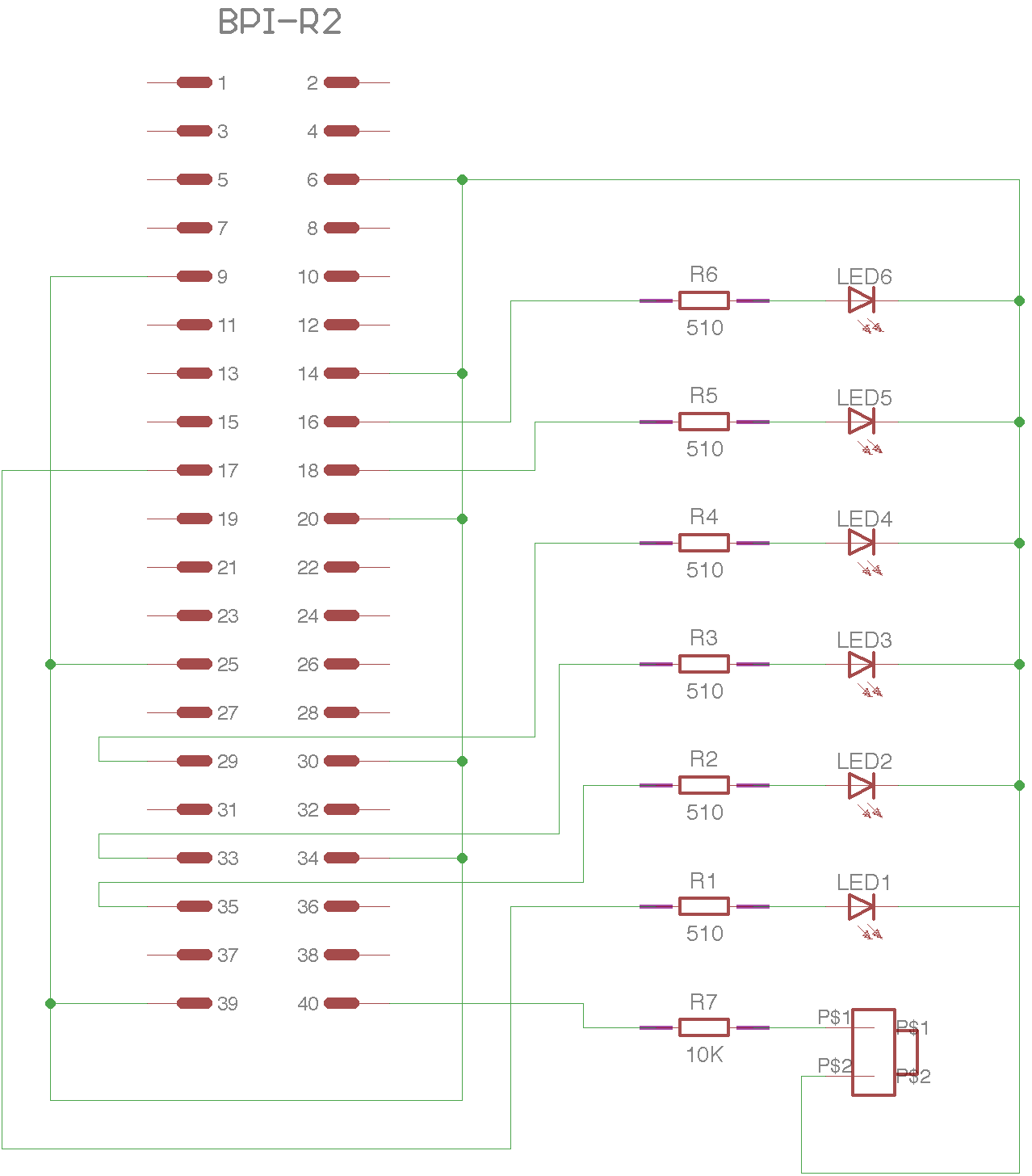 this my scheme