a figure explains concept for duty cycle
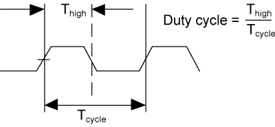
a figure explains concept for duty cycle
so 50%:100% 
so 1kHz should be period of 1000 (if defined 1/Hz) and duty cycle is 0.5 (if high/low is 50:50)
that why i don’t understand the values above (200000 as period and 100000 as duty_cycle)…there duty cycle seems to be not the relationship (it’s the absolute value)…and the values are not 1/Hz
how to do it with 4.14 (debugfs)? and where are pwm 1,4 and 5?
4.14 has to follow official document as you can see in the followin link https://www.kernel.org/doc/Documentation/pwm.txt
and about duty_cycle, period you’re confused about also being defined here, they all are absolute value
period The total period of the PWM signal (read/write). Value is in nanoseconds and is the sum of the active and inactive time of the PWM.
duty_cycle The active time of the PWM signal (read/write). Value is in nanoseconds and must be less than the period.
the pwm kernel exports always in starting at 1. but schematic always starts at 0. you must be aware more about this.
pwm3 is then pwm#4 (if starting at 1) regarding to garys table there are pwm0-pwm4 where pwm3 is gpio 206 (pin 7)
So i’m searching pwm0-1 and pwm4…
pwm2 is gpio205/pin15
Thanks, it works on GPIO 126 or any other than GPIO 200 (PIN 40)
tested with kernel 4.14:
some calculations and export:
[10:51] root@bpi-r2:~# GPIO_NO=$((232+200))
[10:53] root@bpi-r2:~# echo $GPIO_NO
432
[10:53] root@bpi-r2:~# echo $GPIO_NO > /sys/class/gpio/export
first try with LED, if GPIO is right:
[10:53] root@bpi-r2:~# echo out > /sys/class/gpio/gpio${GPIO_NO}/direction
[10:53] root@bpi-r2:~# echo 1 > /sys/class/gpio/gpio${GPIO_NO}/value
[10:54] root@bpi-r2:~# echo 0 > /sys/class/gpio/gpio${GPIO_NO}/value
LED goes on on “1” and off on “0”, so now try with high-active button-circuit on GPIO 200 (pin 40 between button and resistor, using pin 39 as GND [resistor] and pin 17 as 3v3-vcc)
[10:54] root@bpi-r2:~# echo in > /sys/class/gpio/gpio${GPIO_NO}/direction
[10:56] root@bpi-r2:~# cat /sys/class/gpio/gpio${GPIO_NO}/value
0 #button not pressed
[10:56] root@bpi-r2:~# cat /sys/class/gpio/gpio${GPIO_NO}/value
1 #button pressed
[10:56] root@bpi-r2:~# cat /sys/class/gpio/gpio${GPIO_NO}/value
0 #button not pressed
as you see, it works
can you explain me why this:
root@bpi-r2:~# echo 3 >/sys/class/pwm/pwmchip0/export
root@bpi-r2:~# echo 200000 >/sys/class/pwm/pwmchip0/pwm3/period
root@bpi-r2:~# echo 100000 >/sys/class/pwm/pwmchip0/pwm3/duty_cycle
root@bpi-r2:~# echo 1 >/sys/class/pwm/pwmchip0/pwm3/enable
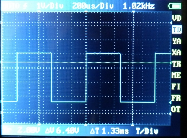
results in 1kHz-PWM? if period is full time (high+low) and in nanoseconds, it should be
200 000 ns = 200 µs = 0,2 ms = 0,0002 s => 1/0.0002 = 5000=5kHz
for 1 kHz period should be 1000000ns and dutycycle 500000ns, or am i’m wrong?
You should be right. I guessed it should be driver problems. I will try to have more analysis when I have free time.
that should be the relevant part (looks right so far):
static int mtk_pwm_config(struct pwm_chip *chip, struct pwm_device *pwm,
			  int duty_ns, int period_ns)
{
	struct mtk_pwm_chip *pc = to_mtk_pwm_chip(chip);
	struct clk *clk = pc->clks[MTK_CLK_PWM1 + pwm->hwpwm];
	u32 resolution, clkdiv = 0;
	int ret;

	ret = mtk_pwm_clk_enable(chip, pwm);
	if (ret < 0)
		return ret;

	resolution = NSEC_PER_SEC / clk_get_rate(clk);

	while (period_ns / resolution > 8191) {
		resolution *= 2;
		clkdiv++;
	}

    mtk_pwm_writel(pc, pwm->hwpwm, PWMCON, BIT(15) | clkdiv);
    if (pwm->hwpwm > 2) { //for PWM4 and PWM5
        mtk_pwm_writel(pc, pwm->hwpwm, PWM45DWIDTH, period_ns / resolution);
        mtk_pwm_writel(pc, pwm->hwpwm, PWM45THRES, duty_ns / resolution);
    }else{
        mtk_pwm_writel(pc, pwm->hwpwm, PWMDWIDTH, period_ns / resolution);
        mtk_pwm_writel(pc, pwm->hwpwm, PWMTHRES, duty_ns / resolution);
    }
    mtk_pwm_clk_disable(chip, pwm);
i assume that there is a Problem in “resolution = NSEC_PER_SEC / clk_get_rate(clk);”
tried adding “resolution = resolution / 5;” after the while-loop, but now i’m getting 730 Hz
so i assume the problem in clkdiv-line “mtk_pwm_writel(pc, pwm->hwpwm, PWMCON, BIT(15) | clkdiv);”
added now 2 printk’s:
root@bpi-r2:~# echo 200000 >/sys/class/pwm/pwmchip0/pwm3/period
root@bpi-r2:~# echo 100000 >/sys/class/pwm/pwmchip0/pwm3/duty_cycle
[   42.063060] [mtk_pwm_config] period_ns: 200000, duty_ns: 100000
[   42.068179] [mtk_pwm_config] resolution: 48, clkdiv: 4
can you verify that is correct?
anything new about the wrong frequency and the missing PWM-Pins?
Hi, Frank
Could you help to test if the issue can be fixup after making the below changes which use clocks all from 26M instead of the old ones.
pwm: pwm@11006000 {
        compatible = "mediatek,mt7623-pwm";
        reg = <0 0x11006000 0 0x1000>;
        #pwm-cells = <2>;
        clocks = <&clk26m>,
                 <&clk26m,
                 <&clk26m>,
                 <&clk26m>,
                 <&clk26m>,
                 <&clk26m>,
                 <&clk26m>;
        clock-names = "top", "main", "pwm1", "pwm2",
                      "pwm3", "pwm4", "pwm5";
        status = "disabled";
};currently it seems to do nothing, no output on pwm3 (pin 7+9)
root@bpi-r2:~# echo 3 >/sys/class/pwm/pwmchip0/export
root@bpi-r2:~# echo 200000 >/sys/class/pwm/pwmchip0/pwm3/period
[  130.864219] [mtk_pwm_config] period_ns: 200000, duty_ns: 0
root@bpi-r2:~# echo 100000 >/sys/class/pwm/pwmchip0/pwm3/duty_cycle
[  130.864230] [mtk_pwm_config] resolution: 38, clkdiv: 0
[  140.144237] [mtk_pwm_config] period_ns: 200000, duty_ns: 100000
root@bpi-r2:~# echo 1 >/sys/class/pwm/pwmchip0/pwm3/enable
btw. you have a typo in second clock-line (missing “>”)
reverted the change and i got the 1kHz (instead of 5kHz) again
anything new to PWM-frequency-bug?
Can you add more 4-times division into the equation and test again? I think it should be internal clock factor is missing in the clock driver for PWM.
as doing that
clock = clk_get_rate(clk) / 4;
resolution = NSEC_PER_SEC / clock;
and not to do as that
resolution = NSEC_PER_SEC / clk_get_rate(clk) / 4;
it would cause more precision is losing.
Using old clock,right? clk26m results in no output
please drop old patch with 26Mhz. and use original code as 4.14 kernel is using.
1kHz without /4 and with it again no output
[  780.909447] [mtk_pwm_config] period_ns: 200000, duty_ns: 0
[  780.909457] [mtk_pwm_config] resolution: 0, clkdiv: 0
[  784.029473] [mtk_pwm_config] period_ns: 200000, duty_ns: 100000
changed that “/ 4” in my main-branch codebase (not commited/pushed)
So weird. do you ensure you add more 4-times divisor based on the code you have done below testing?
Sorry, did it like in your second example…i try the first one tomorrow
Edit: its more near 5kHz 
How preceise should it be?
[   73.950379] [mtk_pwm_config] clock: 68250000, clockrate: 273000000
[   73.950390] [mtk_pwm_config] period_ns: 200000, duty_ns: 0
[   73.950396] [mtk_pwm_config] resolution: 28, clkdiv: 1
[   76.910445] [mtk_pwm_config] clock: 68250000, clockrate: 273000000
[   76.910455] [mtk_pwm_config] period_ns: 200000, duty_ns: 100000
diff (added alternative calculation without additional variable) :
diff --git a/drivers/pwm/pwm-mediatek.c b/drivers/pwm/pwm-mediatek.c
index 1cc2f68..5aa6c4f 100644
--- a/drivers/pwm/pwm-mediatek.c
+++ b/drivers/pwm/pwm-mediatek.c
@@ -121,13 +121,18 @@ static int mtk_pwm_config(struct pwm_chip *chip, struct pwm_device *pwm,
        struct mtk_pwm_chip *pc = to_mtk_pwm_chip(chip);
        struct clk *clk = pc->clks[MTK_CLK_PWM1 + pwm->hwpwm];
        u32 resolution, clkdiv = 0;
+       ulong clock;
        int ret;

        ret = mtk_pwm_clk_enable(chip, pwm);
        if (ret < 0)
                return ret;

-       resolution = NSEC_PER_SEC / clk_get_rate(clk);
+       clock=clk_get_rate(clk) / 4;
+       printk(KERN_NOTICE "[mtk_pwm_config] clock: %lu, clockrate: %lu",clock,clk_get_rate(clk));
+
+       //resolution = NSEC_PER_SEC / ( clk_get_rate(clk) / 4 );
+       resolution = NSEC_PER_SEC / clock;

        while (period_ns / resolution > 8191) {
                resolution *= 2;
…
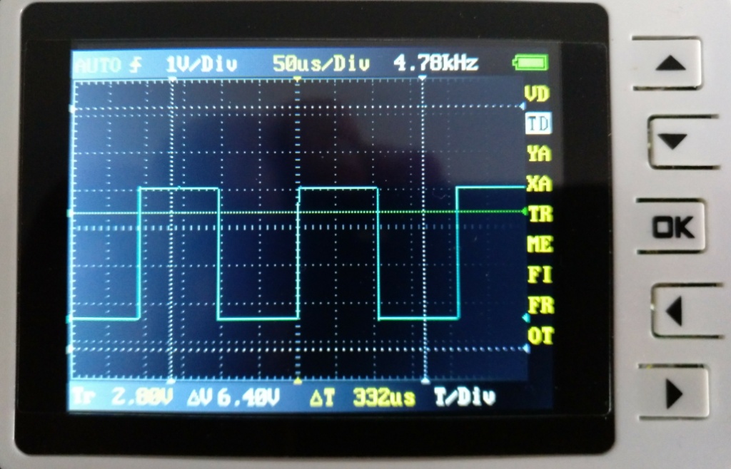
[20:43] root@bpi-r2:~# echo 100000 >/sys/class/pwm/pwmchip0/pwm3/period
[20:45] root@bpi-r2:~# echo 50000 >/sys/class/pwm/pwmchip0/pwm3/duty_cycle
is 9.55kHz
[20:45] root@bpi-r2:~# echo 1000000 >/sys/class/pwm/pwmchip0/pwm3/period
[20:46] root@bpi-r2:~# echo 500000 >/sys/class/pwm/pwmchip0/pwm3/duty_cycle
is 955 Hz
[20:47] root@bpi-r2:~# echo 10000000 >/sys/class/pwm/pwmchip0/pwm3/period
[20:50] root@bpi-r2:~# echo 5000000 >/sys/class/pwm/pwmchip0/pwm3/duty_cycle
95.5 Hz
so the clock(-divider) is a bit inaccurately…can you confirm, that these values are correct depending on Hardware-spec:
clock: 68250000, clockrate: 273000000Seems this is related: https://patchwork.kernel.org/patch/10250319/ + https://patchwork.kernel.org/patch/10250321/