@Maciek_Szelagowski try uart debug , afaik LEDE does not desktop interface
I`m not able to boot the image from microSD card. Not LEDE, nor Ubuntu Mate. I follow all the instructions on how to format the card and burn the image. I did it many times in Linux. Tried in Windows too. Even used two different cards. But whatever I do, the booting from card freezes soon with pink screen and green and red LEDs next to GPIO and the red one next to HDMI on. No prompt appears. Keyboard and mouse do not work. Am I missing something? Or is my BPI-R2 broken? Already two similar posts here in this thread. But no solution so far. I do appreciate any help. Thx.
sunarowicz, You need to connect uart and post a bootlog here.
Thank you for trying to help. But unfortunately I cannot follow your advice. I dont have uart device and dont know how to use it. I`m not an microelectronics guru. Just a guy who immediately bought BPI-R2 once heard about it because have been waiting for years for such board having everything needed for small home server. And expected it will just work…
Banana pi BPI-R2 LEDE source code for hardware NAT
OK guys, so I bought the USB2UART adapter, wired it with my BPI-R2 and got bootlog in Minicom. I was really surprised that the UART thing worked and how easy it was to set it up.
Below is LEDE bootlog. I don’t see anything suspicious there. But to be honest, I don’t understand the content much. Just few seconds after the BPI-R2> prompt appears, the cursor in Minicom freezes. And just pink color on the screen connected to BPI-R2. Attached keyboard not working (even keyboard LED don’t lights).
> [USBD] USB PRB0 LineState: 0
>
> [USBD] USB cable/ No Cable inserted!
>
> [PLFM] Keep stay in USB Mode
> Platform initialization is ok
> wait for frequency meter finish, CLK26CALI = 0x81
> mt_pll_post_init: mt_get_cpu_freq = 1040000Khz
> wait for frequency meter finish, CLK26CALI = 0x90
> mt_pll_post_init: mt_get_bus_freq = 273000Khz
> wait for frequency meter finish, CLK26CALI = 0x81
> mt_pll_post_init: mt_get_mem_freq = 133250Khz
> [PWRAP] pwrap_init_preloader
> [PWRAP] pwrap_init
> [PWRAP] _pwrap_init_sistrobe [Read Test] fail,index=0,rdata=2D52
> [PWRAP] _pwrap_init_sistrobe [Read Test] fail,index=1,rdata=2D52
> [PWRAP] _pwrap_init_sistrobe [Read Test] fail,index=2,rdata=2D52
> [PWRAP] _pwrap_init_sistrobe [Read Test] fail,index=3,rdata=800
> [PWRAP] _pwrap_init_sistrobe [Read Test] pass,index=4 rdata=5AA5
> [PWRAP] _pwrap_init_sistrobe [Read Test] pass,index=5 rdata=5AA5
> [PWRAP] _pwrap_init_sistrobe [Read Test] pass,index=6 rdata=5AA5
> [PWRAP] _pwrap_init_sistrobe [Read Test] pass,index=7 rdata=5AA5
> [PWRAP] _pwrap_init_sistrobe [Read Test] pass,index=8 rdata=5AA5
> [PWRAP] _pwrap_init_sistrobe [Read Test] pass,index=9 rdata=5AA5
> [PWRAP] _pwrap_init_sistrobe [Read Test] pass,index=10 rdata=5AA5
> [PWRAP] _pwrap_init_sistrobe [Read Test] fail,index=11,rdata=1001
> [PWRAP] _pwrap_init_sistrobe [Read Test] fail,index=12,rdata=B54B
> [PWRAP] _pwrap_init_sistrobe [Read Test] fail,index=13,rdata=B54B
> [PWRAP] _pwrap_init_sistrobe [Read Test] fail,index=14,rdata=B54B
> [PWRAP] _pwrap_init_sistrobe [Read Test] fail,index=15,rdata=B54B
> [PWRAP] _pwrap_init_sistrobe [Read Test] fail,index=16,rdata=B54B
> [PWRAP] _pwrap_init_sistrobe [Read Test] fail,index=17,rdata=B54B
> [PWRAP] _pwrap_init_sistrobe [Read Test] fail,index=18,rdata=B54B
> [PWRAP] _pwrap_init_sistrobe [Read Test] fail,index=19,rdata=2003
> [PWRAP] _pwrap_init_sistrobe [Read Test] fail,index=20,rdata=6A97
> [PWRAP] _pwrap_init_sistrobe [Read Test] fail,index=21,rdata=6A97
> [PWRAP] _pwrap_init_sistrobe [Read Test] fail,index=22,rdata=6A97
> [PWRAP] _pwrap_init_sistrobe [Read Test] fail,index=23,rdata=6A97
> [PWRAP] _pwrap_init_reg_clock
> [PMIC_WRAP]wrap_init pass,the return value=0.
> [pmic6323_init] Preloader Start..................
> [pmic6323_init] PMIC CHIP Code = 0x2023
> INT_MISC_CON: 1  TOP_RST_MISC: 1
> pl pmic powerkey Release
> [pmic6323_init] powerKey = 0
> [pmic6323_init] is USB in = 0xB004
> [pmic6323_init] Reg[0x11A]=0x1B
> pmic setup LED
> [pmic6323_init] Done...................
> mt7623 disable long press reset ->>>>>
> mt7623 disable long press reset <<<<<-
> mt7623 VPA supplied by 1.0V to MT7530 ->
> mt7623 VPA supplied by 1.0V to MT7530 <-
> mt7623 enables RG_VGP1_EN for LCM ->
> mt7623 enables RG_VGP1_EN for LCM <-
> MT7623 E2 setting =>
> MT7623 E2 setting <=
> [PLFM] Init I2C: OK(0)
> [PLFM] Init PWRAP: OK(0)
> [PLFM] Init PMIC: OK(0)
> [PLFM] chip[CA00]

> [BLDR] [Support SD/eMMC] Build Time: 20170905-112929
> ==== Dump RGU Reg ========
> RGU MODE:     4D
> RGU LENGTH:   FFE0
> RGU STA:      0
> RGU INTERVAL: FFF
> RGU SWSYSRST: 0
> ==== Dump RGU Reg End ====
> RGU: g_rgu_satus:0
>  mtk_wdt_mode_config  mode value=10, tmp:22000010
> PL P ON
> WDT does not trigger reboot
> RGU mtk_wdt_init:MTK_WDT_DEBUG_CTL(590200F3)
> kpd read addr: 0x0040: data:0x4001
> Enter mtk_kpd_gpio_set!
> kpd debug column : 0, 0, 0, 0, 0, 0, 0, 0
> kpd debug row : 0, 0, 0, 0, 0, 0, 0, 0
> after set KP enable: KP_SEL = 0x0 !
> MTK_PMIC_RST_KEY is used for this project!
> [RTC] get_frequency_meter: input=0x0, ouput=5
> [RTC] get_frequency_meter: input=0x0, ouput=3967
> [RTC] get_frequency_meter: input=0x0, ouput=5
> [RTC] get_frequency_meter: input=0x0, ouput=0
> [RTC] get_frequency_meter: input=0x0, ouput=0
> [RTC] bbpu = 0xD, con = 0x426
> [RTC] powerkey1 = 0xA357, powerkey2 = 0x67D2
> Writeif_unlock
> [RTC] RTC_SPAR0=0x40
> rtc_2sec_reboot_check cali=1280
> rtc_2sec_stat_clear
> [RTC] irqsta = 0x0, pdn1 = 0x0, pdn2 = 0x201, spar0 = 0x40, spar1 = 0x800
> [RTC] new_spare0 = 0x0, new_spare1 = 0x1, new_spare2 = 0x1, new_spare3 = 0x1
> [RTC] bbpu = 0xD, con = 0x426, cali = 0x500
> pl pmic powerkey Release
> [PLFM] Power key boot!
> [RTC] rtc_bbpu_power_on done
> [EMI] mcp_dram_num:0,discrete_dram_num:1,enable_combo_dis:0
> [EMI] PCDDR3
> [Check]mt_get_mdl_number 0x0
> [EMI] eMMC/NAND ID = 0,0,0,0,0,0,0,0,0,0,0,0,0,0,0,0
> [EMI] MDL number = 0
> [EMI] emi_set eMMC/NAND ID = 0,0,0,0,0,0,0,0,0,0,0,0,0,0,0,0
> [EMI][Vcore]0x21E=0x48,0x220=0x48
> [EMI][Vmem]0x554=0x0
> wait for frequency meter finish, CLK26CALI = 0x81
> [EMI] PCDDR3 DRAM Clock = 1600012 KHz, MEMPLL MODE = 2
> [EMI] PCDDR3 RXTDN Calibration:
> Start REXTDN SW calibration...
> drvp=0xB,drvn=0x9
> [EMI] pinmux = 4
> ===============================================================================

>         dramc_write_leveling_swcal
> ===============================================================================
> delay  byte0  byte1  byte2  byte3
> -----------------------------
> 0    0    0    0    1
> 1    0    0    0    1
> 2    0    0    1    1
> 3    0    0    1    1
> 4    0    1    1    1
> 5    0    1    1    1
> 6    0    1    1    1
> 7    0    1    1    1
> 8    0    1    1    1
> 9    1    1    1    1
> 10    1    1    1    1
> 11    1    1    1    1
> 12    1    1    1    1
> 13    1    1    1    1
> 14    1    1    1    1
> 15    1    1    1    1
> pass bytecount = 4
> byte_i    status    best delay
> 0    2    9
> 1    2    4
> 2    2    2
> 3    2    0
> ========================================
> [write leveling]DQS: 0x249, DQM: 0x249
> [write leveling after remap]DQ byte0 reg: 0x200 val: 0x99994444
> [write leveling after remap]DQ byte1 reg: 0x204 val: 0x44449999
> [write leveling after remap]DQ byte2 reg: 0x208 val: 0x22220000
> [write leveling after remap]DQ byte3 reg: 0x20C val: 0x2222
> =============================================
> X-axis: DQS Gating Window Delay (Fine Scale)
> Y-axis: DQS Gating Window Delay (Coarse Scale)
> =============================================
>           0    8   16   24   32   40   48   56   64   72   80   88   96  104  112  120
>       --------------------------------------------------------------------------------
> 0000:|    0    0    0    0    0    0    0    0    0    0    0    0    0    0    0    0
> 0001:|    0    0    0    0    0    0    0    0    0    0    0    0    0    0    0    0
> 0002:|    0    0    0    0    0    0    0    0    0    0    0    0    0    0    0    0
> 0003:|    0    0    0    0    0    0    0    0    0    0    0    0    0    0    0    0
> 0004:|    0    0    0    0    0    0    0    0    0    0    0    0    0    0    0    0
> 0005:|    0    0    0    0    0    0    0    0    0    0    0    0    0    0    0    0
> 0006:|    0    0    0    0    0    0    0    0    0    0    0    0    0    0    0    0
> 0007:|    0    0    0    0    0    0    0    0    0    0    0    0    0    0    0    0
> 0008:|    0    0    0    0    0    0    0    0    0    0    0    0    0    0    0    0
> 0009:|    0    0    0    0    0    0    0    0    0    0    0    0    0    0    0    0
> 000A:|    0    0    0    0    0    0    0    0    0    0    0    0    0    0    0    0
> 000B:|    0    0    0    0    0    0    0    0    0    0    0    0    0    0    0    0
> 000C:|    0    0    0    0    0    0    0    0    0    0    0    0    0    0    0    0
> 000D:|    0    0    0    0    0    0    0    0    0    0    0    0    0    0    0    0
> 000E:|    0    0    0    0    0    0    0    0    0    0    0    0    0    0    0    0
> 000F:|    0    0    0    0    0    0    0    0    0    0    0    0    0    0    0    0
> 0010:|    0    0    0    0    0    0    0    0    0    0    0    0    0    0    0    1
> 0011:|    0    0    0    0    0    0    0    0    0    1    1    1    1    1    1    1
> 0012:|    0    0    0    0    1    1    1    1    1    1    1    1    1    1    0    0
> 0013:|    1    1    1    1    1    1    1    1    0    0    0    0    0    0    0    0
> 0014:|    1    1    1    0    0    0    0    0    0    0    0    0    0    0    0    0
> 0015:|    0    0    0    0    0    0    0    0    0    0    0    0    0    0    0    0
> 0016:|    0    0    0    0    0    0    0    0    0    0    0    0    0    0    0    0
> 0017:|    0    0    0    0    0    0    0    0    0    0    0    0    0    0    0    0
> 0018:|    0    0    0    0    0    0    0    0    0    0    0    0    0    0    0    0
> 0019:|    0    0    0    0    0    0    0    0    0    0    0    0    0    0    0    0
> 001A:|    0    0    0    0    0    0    0    0    0    0    0    0    0    0    0    0
> 001B:|    0    0    0    0    0    0    0    0    0    0    0    0    0    0    0    0
> 001C:|    0    0    0    0    0    0    0    0    0    0    0    0    0    0    0    0
> 001D:|    0    0    0    0    0    0    0    0    0    0    0    0    0    0    0    0
> 001E:|    0    0    0    0    0    0    0    0    0    0    0    0    0    0    0    0
> 001F:|    0    0    0    0    0    0    0    0    0    0    0    0    0    0    0    0
> Rank 0 coarse tune value selection : 18, 18
> 18
> 72
> rank 0 coarse = 18
> rank 0 fine = 72
> 00:|    0    0    0    0    0    0    0    0    1    1    1    0
> opt_dle value:13
> ==================================================================
>                 RX      DQS perbit delay software calibration
> ==================================================================
> 1.0-31 bit dq delay value
> ==================================================================
> bit|     0  1  2  3  4  5  6  7  8  9
> --------------------------------------
> 0 |    0 0 0 0 0 0 0 0 0 0
> 10 |    0 0 0 0 0 0 0 0 0 0
> 20 |    0 0 0 0 0 0 0 0 0 0
> 30 |    0 0
> --------------------------------------
> ==================================================================
> 2.dqs window
> x=pass dqs delay value (min~max)center
> y=0-7bit DQ of every group
> input delay:DQS0 =51 DQS1 = 42 DQS2 =52 DQS3 = 45
> ==================================================================
> bit     DQS0     bit      DQS1     bit     DQS2     bit     DQS3
> 0  (20~69)44  8  (11~61)36  16  (22~67)44  24  (17~63)40
> 1  (20~70)45  9  (8~62)35  17  (23~72)47  25  (17~62)39
> 2  (21~70)45  10  (11~64)37  18  (24~70)47  26  (19~62)40
> 3  (21~68)44  11  (13~62)37  19  (21~69)45  27  (20~64)42
> 4  (21~72)46  12  (17~63)40  20  (25~78)51  28  (23~67)45
> 5  (21~68)44  13  (14~63)38  21  (23~69)46  29  (21~65)43
> 6  (23~70)46  14  (13~61)37  22  (23~72)47  30  (19~62)40
> 7  (27~76)51  15  (18~66)42  23  (29~75)52  31  (19~64)41
> ==================================================================
> 3.dq delay value last
> ==================================================================
> bit|    0  1  2  3  4  5  6  7  8   9
> --------------------------------------
> 0 |    7 6 6 7 5 7 5 0 6 7
> 10 |    5 5 2 4 5 0 8 5 5 7
> 20 |    1 6 5 0 5 6 5 3 0 2
> 30 |    5 4
> ==================================================================
> *DQIDLY1 = 0x7060607
> *DQIDLY2 = 0x50705
> *DQIDLY3 = 0x5050706
> *DQIDLY4 = 0x50402
> *DQIDLY5 = 0x7050508
> *DQIDLY6 = 0x50601
> *DQIDLY7 = 0x3050605
> *DQIDLY8 = 0x4050200
> *DRAMC_R0DELDLY = 0x2D342A33

> [MEM]CONA:F3A2,conf1:F07486A3
> DM4BitMux = 1
> DQSO 0 in TX per-bit = 2 <= DQSO 0 in WL = 9
> DQSO 1 in TX per-bit = 0 <= DQSO 1 in WL = 4
> [Warning] DQSO 2 in TX per-bit = 8 > DQSO 2 in WL = 2
> [Warning] DQSO 3 in TX per-bit = 6 > DQSO 3 in WL = 0
> Tx DQM dly  = 0x1189
> Tx DQM dly bit4 = 0x0
> DRAMC_DQODLY1=79AA8899h
> DRAMC_DQODLY2=9A78B9AAh
> DRAMC_DQODLY3=1202112h
> DRAMC_DQODLY4=22102113h
> Tx DQ dly bit4 = 0x0
> Tx DQS dly = 0x6849
> Tx DQS dly bit4 = 0x0
> TX Byte0: DQ - 16, DQS - 18. win_sum= 33
> TX Byte1: DQ - 20, DQS - 12. win_sum= 31
> TX Byte2: DQ - 9, DQS - 22. win_sum= 30
> TX Byte3: DQ - 10, DQS - 20. win_sum= 29
> DRAMC calibration takes 651544846 CPU cycles

> [EMI] DRAMC calibration passed

> [MEM] complex R/W mem test pass
> 0:dram_rank_size:80000000
> [Dram_Buffer] dram size:-2147483648
> [Dram_Buffer] structure size: 1725560
> [Dram_Buffer] MAX_TEE_DRAM_SIZE: 0
> Load u-boot from SD Card...
> [PLFM] Init Boot Device: OK(0)

> [PART] blksz: 512B
> [PART] [0x0000000000000000-0x000000000003FFFF] "PRELOADER" (512 blocks)
> [PART] [0x0000000000000000-0x000000000003FFFF] "MBR" (512 blocks)
> [PART] [0x0000000000040000-0x00000000000BFFFF] "UBOOT" (1024 blocks)
> [PART] [0x00000000000C0000-0x00000000000FFFFF] "CONFIG" (512 blocks)
> [PART] [0x0000000000100000-0x000000000013FFFF] "FACTORY" (512 blocks)
> [PART] [0x0000000000140000-0x000000000213FFFF] "BOOTIMG" (65536 blocks)
> [PART] [0x0000000002140000-0x000000000413FFFF] "RECOVERY" (65536 blocks)
> [PART] [0x0000000004140000-0x000000004413FFFF] "ROOTFS" (2097152 blocks)
> [PART] [0x0000000044140000-0x000001FFC413FFFF] "USER" (-4194304 blocks)
> [platform_vusb_on] PASS
> [TOOL] PMIC not dectect usb cable!
> [TOOL] <UART> listen  ended, receive size:0!
> [TOOL] <UART> wait sync time 150ms->5ms
> [TOOL] <UART> receieved data: ()

> Device APC domain init setup:

>  bootloader load uboot ,the address of uboot is 81E00000
> [PART]partition name UBOOT
> [PART]partition start block 0x200
> [PART]partition size 0x80000
> [PART]partition blks 0x400
> [PART]partition flags 0x0
> [PART]partition name 0x8
> [bean] part->startblk(0x200) bdev->blksz(0x200) part->part_id(8) hdr(0xFFB50000)
> [BlkDev.c 101 ]partition block size 0x200 ,blks:0x3A4000
> [BlkDev.c 101 ]partition block erase size 0x200

> [PART] load "UBOOT" from 0x0000000000050000 (dev) to 0x81E00000 (mem) [SUCCESS]
> [PART] load speed: 5424KB/s, 300000 bytes, 54ms
> [BT_SD_PG] device info 0x8590 0x8A00 0xCB01 0x102
> 0:dram_rank_size:80000000
> [PLFM] md_type[0] = 0
> [PLFM] md_type[1] = 0

> [PLFM] boot reason: 0
> [PLFM] boot mode: 0
> [PLFM] META COM0: 0
> [PLFM] <0xFFB7CC10>: 0x0
> [PLFM] boot time: 1895ms
> [PLFM] DDR reserve mode: enable = 0, success = 0

> [BLDR] jump to 0x81E00000
> [BLDR] <0x81E00000>=0xEA00000F
> [BLDR] <0x81E00004>=0xE59FF014


> U-Boot 2014.04-rc1 (Sep 05 2017 - 12:43:27)

> g_nr_bank = 1.
> g_total_rank_size = 0x80000000
> DRAM:  2 GiB
> WARNING: Caches not enabled
> MMC:     emmc: 0,  sdcard: 1
> dev_num = 1
> ***size=16384, offset=1048576, blk_start=2048, blk_cnt=32
> In:    serial
> Out:   serial
> Err:   serial
> Net:   Eth0
> Uip activated
> Hit any key to stop autoboot:  0
> dev_num = 1
> mmc1 is current device
> dev_num = 1

> MMC read: dev # 1, block # 25856, count 512 ... 512 blocks read: OK
> dev_num = 0
> mmc0 is current device
> dev_num = 0

> eMMC write: part # 1, block # 0, count 512 ... 512 blocks write: OK
> dev_num = 1
> mmc1 is current device
> dev_num = 1

> MMC read: dev # 1, block # 26368, count 512 ... 512 blocks read: OK
> dev_num = 0
> mmc0 is current device
> dev_num = 0

> MMC write: dev # 0, block # 640, count 512 ... 512 blocks write: OK
> dev_num = 1
> mmc1 is current device
> dev_num = 1

> MMC read: dev # 1, block # 4096, count 21760 ... 21760 blocks read: OK
> dev_num = 0
> mmc0 is current device
> dev_num = 0

> MMC write: dev # 0, block # 4096, count 21760 ... 21760 blocks write: OK
> BPI-R2>

According to the bootlog LEDE seems to be copied in EMMC. So I powered off, removed the SD card and tried to power on without SD card as LEDE should be already in EMMC. But it didn't work. I pressed the power buton for 30 seconds and it didn't start booting. So it seems that LEDE is not in EMMC as it should be.

Bellow I add the bootlog from booting the Ubuntu Mate from SD card. The result is the same as with LEDE. Booting freezes with pink screen and keyboard and mouse not working.

> [USBD] USB PRB0 LineState: 0

> [USBD] USB cable/ No Cable inserted!

> [PLFM] Keep stay in USB Mode
> Platform initialization is ok
> wait for frequency meter finish, CLK26CALI = 0x81
> mt_pll_post_init: mt_get_cpu_freq = 1040000Khz
> wait for frequency meter finish, CLK26CALI = 0x90
> mt_pll_post_init: mt_get_bus_freq = 273000Khz
> wait for frequency meter finish, CLK26CALI = 0x81
> mt_pll_post_init: mt_get_mem_freq = 133250Khz
> [PWRAP] pwrap_init_preloader
> [PWRAP] pwrap_init
> [PWRAP] _pwrap_init_sistrobe [Read Test] fail,index=0,rdata=2D52
> [PWRAP] _pwrap_init_sistrobe [Read Test] fail,index=1,rdata=2D52
> [PWRAP] _pwrap_init_sistrobe [Read Test] fail,index=2,rdata=2D52
> [PWRAP] _pwrap_init_sistrobe [Read Test] fail,index=3,rdata=800
> [PWRAP] _pwrap_init_sistrobe [Read Test] pass,index=4 rdata=5AA5
> [PWRAP] _pwrap_init_sistrobe [Read Test] pass,index=5 rdata=5AA5
> [PWRAP] _pwrap_init_sistrobe [Read Test] pass,index=6 rdata=5AA5
> [PWRAP] _pwrap_init_sistrobe [Read Test] pass,index=7 rdata=5AA5
> [PWRAP] _pwrap_init_sistrobe [Read Test] pass,index=8 rdata=5AA5
> [PWRAP] _pwrap_init_sistrobe [Read Test] pass,index=9 rdata=5AA5
> [PWRAP] _pwrap_init_sistrobe [Read Test] pass,index=10 rdata=5AA5
> [PWRAP] _pwrap_init_sistrobe [Read Test] fail,index=11,rdata=1001
> [PWRAP] _pwrap_init_sistrobe [Read Test] fail,index=12,rdata=B54B
> [PWRAP] _pwrap_init_sistrobe [Read Test] fail,index=13,rdata=B54B
> [PWRAP] _pwrap_init_sistrobe [Read Test] fail,index=14,rdata=B54B
> [PWRAP] _pwrap_init_sistrobe [Read Test] fail,index=15,rdata=B54B
> [PWRAP] _pwrap_init_sistrobe [Read Test] fail,index=16,rdata=B54B
> [PWRAP] _pwrap_init_sistrobe [Read Test] fail,index=17,rdata=B54B
> [PWRAP] _pwrap_init_sistrobe [Read Test] fail,index=18,rdata=B54B
> [PWRAP] _pwrap_init_sistrobe [Read Test] fail,index=19,rdata=2003
> [PWRAP] _pwrap_init_sistrobe [Read Test] fail,index=20,rdata=6A97
> [PWRAP] _pwrap_init_sistrobe [Read Test] fail,index=21,rdata=6A97
> [PWRAP] _pwrap_init_sistrobe [Read Test] fail,index=22,rdata=6A97
> [PWRAP] _pwrap_init_sistrobe [Read Test] fail,index=23,rdata=6A97
> [PWRAP] _pwrap_init_reg_clock
> [PMIC_WRAP]wrap_init pass,the return value=0.
> [pmic6323_init] Preloader Start..................
> [pmic6323_init] PMIC CHIP Code = 0x2023
> INT_MISC_CON: 1  TOP_RST_MISC: 1
> pl pmic powerkey Release
> [pmic6323_init] powerKey = 0
> [pmic6323_init] is USB in = 0xB004
> [pmic6323_init] Reg[0x11A]=0x1B
> pmic setup LED
> [pmic6323_init] Done...................
> mt7623 disable long press reset ->>>>>
> mt7623 disable long press reset <<<<<-
> mt7623 VPA supplied by 1.0V to MT7530 ->
> mt7623 VPA supplied by 1.0V to MT7530 <-
> mt7623 enables RG_VGP1_EN for LCM ->
> mt7623 enables RG_VGP1_EN for LCM <-
> MT7623 E2 setting =>
> MT7623 E2 setting <=
> [PLFM] Init I2C: OK(0)
> [PLFM] Init PWRAP: OK(0)
> [PLFM] Init PMIC: OK(0)
> [PLFM] chip[CA00]

> [BLDR] [Support SD/eMMC] Build Time: 20170114-170026
> ==== Dump RGU Reg ========
> RGU MODE:     4D
> RGU LENGTH:   FFE0
> RGU STA:      0
> RGU INTERVAL: FFF
> RGU SWSYSRST: 0
> ==== Dump RGU Reg End ====
> RGU: g_rgu_satus:0
>  mtk_wdt_mode_config  mode value=10, tmp:22000010
> PL P ON
> WDT does not trigger reboot
> RGU mtk_wdt_init:MTK_WDT_DEBUG_CTL(590200F3)
> kpd read addr: 0x0040: data:0x4001
> Enter mtk_kpd_gpio_set!
> kpd debug column : 0, 0, 0, 0, 0, 0, 0, 0
> kpd debug row : 0, 0, 0, 0, 0, 0, 0, 0
> after set KP enable: KP_SEL = 0x0 !
> MTK_PMIC_RST_KEY is used for this project!
> [RTC] get_frequency_meter: input=0x0, ouput=5
> [RTC] get_frequency_meter: input=0x0, ouput=3968
> [RTC] get_frequency_meter: input=0x0, ouput=5
> [RTC] get_frequency_meter: input=0x0, ouput=0
> [RTC] get_frequency_meter: input=0x0, ouput=0
> [RTC] bbpu = 0xD, con = 0x426
> [RTC] powerkey1 = 0xA357, powerkey2 = 0x67D2
> Writeif_unlock
> [RTC] RTC_SPAR0=0x40
> rtc_2sec_reboot_check cali=1280
> rtc_2sec_stat_clear
> [RTC] irqsta = 0x0, pdn1 = 0x0, pdn2 = 0x201, spar0 = 0x40, spar1 = 0x800
> [RTC] new_spare0 = 0x0, new_spare1 = 0x1, new_spare2 = 0x1, new_spare3 = 0x1
> [RTC] bbpu = 0xD, con = 0x426, cali = 0x500
> pl pmic powerkey Release
> [PLFM] Power key boot!
> [RTC] rtc_bbpu_power_on done
> [EMI] mcp_dram_num:0,discrete_dram_num:1,enable_combo_dis:0
> [EMI] PCDDR3
> [Check]mt_get_mdl_number 0x0
> [EMI] eMMC/NAND ID = 0,0,0,0,0,0,0,0,0,0,0,0,0,0,0,0
> [EMI] MDL number = 0
> [EMI] emi_set eMMC/NAND ID = 0,0,0,0,0,0,0,0,0,0,0,0,0,0,0,0
> [EMI][Vcore]0x21E=0x48,0x220=0x48
> [EMI][Vmem]0x554=0x0
> wait for frequency meter finish, CLK26CALI = 0x81
> [EMI] PCDDR3 DRAM Clock = 1600012 KHz, MEMPLL MODE = 2
> [EMI] PCDDR3 RXTDN Calibration:
> Start REXTDN SW calibration...
> drvp=0xB,drvn=0x9
> [EMI] pinmux = 4
> ===============================================================================

>         dramc_write_leveling_swcal
> ===============================================================================
> delay  byte0  byte1  byte2  byte3
> -----------------------------
> 0    0    0    0    1
> 1    0    0    0    1
> 2    0    0    0    1
> 3    0    0    1    1
> 4    0    1    1    1
> 5    0    1    1    1
> 6    0    1    1    1
> 7    0    1    1    1
> 8    0    1    1    1
> 9    0    1    1    1
> 10    1    1    1    1
> 11    1    1    1    1
> 12    1    1    1    1
> 13    1    1    1    1
> 14    1    1    1    1
> 15    1    1    1    1
> pass bytecount = 4
> byte_i    status    best delay
> 0    2    10
> 1    2    4
> 2    2    3
> 3    2    0
> ========================================
> [write leveling]DQS: 0x34A, DQM: 0x34A
> [write leveling after remap]DQ byte0 reg: 0x200 val: 0xAAAA4444
> [write leveling after remap]DQ byte1 reg: 0x204 val: 0x4444AAAA
> [write leveling after remap]DQ byte2 reg: 0x208 val: 0x33330000
> [write leveling after remap]DQ byte3 reg: 0x20C val: 0x3333
> =============================================
> X-axis: DQS Gating Window Delay (Fine Scale)
> Y-axis: DQS Gating Window Delay (Coarse Scale)
> =============================================
>           0    8   16   24   32   40   48   56   64   72   80   88   96  104  112  120
>       --------------------------------------------------------------------------------
> 0000:|    0    0    0    0    0    0    0    0    0    0    0    0    0    0    0    0
> 0001:|    0    0    0    0    0    0    0    0    0    0    0    0    0    0    0    0
> 0002:|    0    0    0    0    0    0    0    0    0    0    0    0    0    0    0    0
> 0003:|    0    0    0    0    0    0    0    0    0    0    0    0    0    0    0    0
> 0004:|    0    0    0    0    0    0    0    0    0    0    0    0    0    0    0    0
> 0005:|    0    0    0    0    0    0    0    0    0    0    0    0    0    0    0    0
> 0006:|    0    0    0    0    0    0    0    0    0    0    0    0    0    0    0    0
> 0007:|    0    0    0    0    0    0    0    0    0    0    0    0    0    0    0    0
> 0008:|    0    0    0    0    0    0    0    0    0    0    0    0    0    0    0    0
> 0009:|    0    0    0    0    0    0    0    0    0    0    0    0    0    0    0    0
> 000A:|    0    0    0    0    0    0    0    0    0    0    0    0    0    0    0    0
> 000B:|    0    0    0    0    0    0    0    0    0    0    0    0    0    0    0    0
> 000C:|    0    0    0    0    0    0    0    0    0    0    0    0    0    0    0    0
> 000D:|    0    0    0    0    0    0    0    0    0    0    0    0    0    0    0    0
> 000E:|    0    0    0    0    0    0    0    0    0    0    0    0    0    0    0    0
> 000F:|    0    0    0    0    0    0    0    0    0    0    0    0    0    0    0    0
> 0010:|    0    0    0    0    0    0    0    0    0    0    0    0    0    0    1    1
> 0011:|    0    0    0    0    0    0    0    0    0    1    1    1    1    1    1    1
> 0012:|    0    0    0    1    1    1    1    1    1    1    1    1    1    1    0    0
> 0013:|    1    1    1    1    1    1    1    1    0    0    0    0    0    0    0    0
> 0014:|    1    1    1    0    0    0    0    0    0    0    0    0    0    0    0    0
> 0015:|    0    0    0    0    0    0    0    0    0    0    0    0    0    0    0    0
> 0016:|    0    0    0    0    0    0    0    0    0    0    0    0    0    0    0    0
> 0017:|    0    0    0    0    0    0    0    0    0    0    0    0    0    0    0    0
> 0018:|    0    0    0    0    0    0    0    0    0    0    0    0    0    0    0    0
> 0019:|    0    0    0    0    0    0    0    0    0    0    0    0    0    0    0    0
> 001A:|    0    0    0    0    0    0    0    0    0    0    0    0    0    0    0    0
> 001B:|    0    0    0    0    0    0    0    0    0    0    0    0    0    0    0    0
> 001C:|    0    0    0    0    0    0    0    0    0    0    0    0    0    0    0    0
> 001D:|    0    0    0    0    0    0    0    0    0    0    0    0    0    0    0    0
> 001E:|    0    0    0    0    0    0    0    0    0    0    0    0    0    0    0    0
> 001F:|    0    0    0    0    0    0    0    0    0    0    0    0    0    0    0    0
> Rank 0 coarse tune value selection : 18, 18
> 18
> 64
> rank 0 coarse = 18
> rank 0 fine = 64
> 00:|    0    0    0    0    0    0    0    0    1    1    1    0
> opt_dle value:13
> ==================================================================
> 		RX	DQS perbit delay software calibration
> ==================================================================
> 1.0-31 bit dq delay value
> ==================================================================
> bit|     0  1  2  3  4  5  6  7  8  9
> --------------------------------------
> 0 |    0 0 0 0 0 0 0 0 0 0
> 10 |    0 0 0 0 0 0 0 0 0 0
> 20 |    0 0 0 0 0 0 0 0 0 0
> 30 |    0 0
> --------------------------------------
> ==================================================================
> 2.dqs window
> x=pass dqs delay value (min~max)center
> y=0-7bit DQ of every group
> input delay:DQS0 =51 DQS1 = 42 DQS2 =52 DQS3 = 45
> ==================================================================
> bit	DQS0	 bit      DQS1     bit     DQS2     bit     DQS3
> 0  (20~69)44  8  (11~61)36  16  (22~67)44  24  (17~62)39
> 1  (20~70)45  9  (8~62)35  17  (23~71)47  25  (17~62)39
> 2  (21~70)45  10  (11~64)37  18  (24~70)47  26  (19~62)40
> 3  (21~68)44  11  (13~62)37  19  (21~68)44  27  (20~63)41
> 4  (21~73)47  12  (17~64)40  20  (25~78)51  28  (23~67)45
> 5  (21~68)44  13  (14~63)38  21  (23~69)46  29  (21~65)43
> 6  (23~70)46  14  (14~61)37  22  (22~72)47  30  (19~62)40
> 7  (27~76)51  15  (18~66)42  23  (29~75)52  31  (19~64)41
> ==================================================================
> 3.dq delay value last
> ==================================================================
> bit|    0  1  2  3  4  5  6  7  8   9
> --------------------------------------
> 0 |    7 6 6 7 4 7 5 0 6 7
> 10 |    5 5 2 4 5 0 8 5 5 8
> 20 |    1 6 5 0 6 6 5 4 0 2
> 30 |    5 4
> ==================================================================
> *DQIDLY1 = 0x7060607
> *DQIDLY2 = 0x50704
> *DQIDLY3 = 0x5050706
> *DQIDLY4 = 0x50402
> *DQIDLY5 = 0x8050508
> *DQIDLY6 = 0x50601
> *DQIDLY7 = 0x4050606
> *DQIDLY8 = 0x4050200
> *DRAMC_R0DELDLY = 0x2D342A33

> [MEM]CONA:F3A2,conf1:F07486A3
> DM4BitMux = 1
> DQSO 0 in TX per-bit = 1 <= DQSO 0 in WL = 10
> DQSO 1 in TX per-bit = 0 <= DQSO 1 in WL = 4
> [Warning] DQSO 2 in TX per-bit = 8 > DQSO 2 in WL = 3
> [Warning] DQSO 3 in TX per-bit = 7 > DQSO 3 in WL = 0
> Tx DQM dly  = 0x117A
> Tx DQM dly bit4 = 0x0
> DRAMC_DQODLY1=9ACB8878h
> DRAMC_DQODLY2=8A77CABBh
> DRAMC_DQODLY3=1203223h
> DRAMC_DQODLY4=22102114h
> Tx DQ dly bit4 = 0x0
> Tx DQS dly = 0x784A
> Tx DQS dly bit4 = 0x0
> TX Byte0: DQ - 16, DQS - 16. win_sum= 31
> TX Byte1: DQ - 20, DQS - 12. win_sum= 31
> TX Byte2: DQ - 10, DQS - 21. win_sum= 30
> TX Byte3: DQ - 10, DQS - 21. win_sum= 30
> DRAMC calibration takes 651748000 CPU cycles

> [EMI] DRAMC calibration passed

> [MEM] complex R/W mem test pass
> 0:dram_rank_size:80000000
> [Dram_Buffer] dram size:-2147483648
> [Dram_Buffer] structure size: 1725560
> [Dram_Buffer] MAX_TEE_DRAM_SIZE: 0
> Boot from SD Card!!
> [PLFM] Init Boot Device: OK(0)

> [PART] blksz: 512B
> [PART] [0x0000000000000000-0x000000000003FFFF] "PRELOADER" (512 blocks)
> [PART] [0x0000000000000000-0x000000000003FFFF] "MBR" (512 blocks)
> [PART] [0x0000000000040000-0x00000000000BFFFF] "UBOOT" (1024 blocks)
> [PART] [0x00000000000C0000-0x00000000000FFFFF] "CONFIG" (512 blocks)
> [PART] [0x0000000000100000-0x000000000013FFFF] "FACTORY" (512 blocks)
> [PART] [0x0000000000140000-0x000000000213FFFF] "BOOTIMG" (65536 blocks)
> [PART] [0x0000000002140000-0x000000000413FFFF] "RECOVERY" (65536 blocks)
> [PART] [0x0000000004140000-0x000000004413FFFF] "ROOTFS" (2097152 blocks)
> [PART] [0x0000000044140000-0x000001FFC413FFFF] "USER" (-4194304 blocks)
> [platform_vusb_on] PASS
> [TOOL] PMIC not dectect usb cable!
> [TOOL] <UART> listen  ended, receive size:0!
> [TOOL] <UART> wait sync time 150ms->5ms
> [TOOL] <UART> receieved data: ()

> Device APC domain init setup:

>  bootloader load uboot ,the address of uboot is 81E00000
> [PART]partition name UBOOT
> [PART]partition start block 0x200
> [PART]partition size 0x80000
> [PART]partition blks 0x400
> [PART]partition flags 0x0
> [PART]partition name 0x8
> [bean] part->startblk(0x200) bdev->blksz(0x200) part->part_id(8) hdr(0xFFB50000)
> [BlkDev.c 101 ]partition block size 0x200 ,blks:0xF07800
> [BlkDev.c 101 ]partition block erase size 0x200

> [PART] load "UBOOT" from 0x0000000000050000 (dev) to 0x81E00000 (mem) [SUCCESS]
> [PART] load speed: 6232KB/s, 300000 bytes, 47ms
> [BT_SD_PG] device info 0x8590 0x8A00 0xCB01 0x102
> 0:dram_rank_size:80000000
> [PLFM] md_type[0] = 255
> [PLFM] md_type[1] = 255

> [PLFM] boot reason: 0
> [PLFM] boot mode: 0
> [PLFM] META COM0: 0
> [PLFM] <0xFFB7CC10>: 0x0
> [PLFM] boot time: 1892ms
> [PLFM] DDR reserve mode: enable = 0, success = 0

> [BLDR] jump to 0x81E00000
> [BLDR] <0x81E00000>=0x5BF6144E
> [BLDR] <0x81E00004>=0x6B99EE8A
Any idea what is wrong? Thx.
Sorry, I was not able to manage to insert bootlogs here as they should be. I tried to insert it as a quotation block and as a code as well, but the result is the same (no EOLs and no vertical scroller)
I connect FT232RL based adapter as follows: RX on adapter to PIN8 on GPIO (TX). TX on adapter to PIN10 on GPIO (RX) set speed to 115200 8 N 1, run putty on windows set to COM3 (my adapter is visible on that address) and nothing happends when I power on my BPI R2. What I could do wrong?
Sorry, I do not have any experience with FT232RL adapter. But today I bought the CP2102 based adapter for little money and it works like a charm at first try. See here: https://www.gme.cz/prevodnik-usb-uart-reset-pin#product-detail.
Have switched to Profilic PL-2303HX and still no luck … I will try if Ubuntu wants to talk on serial
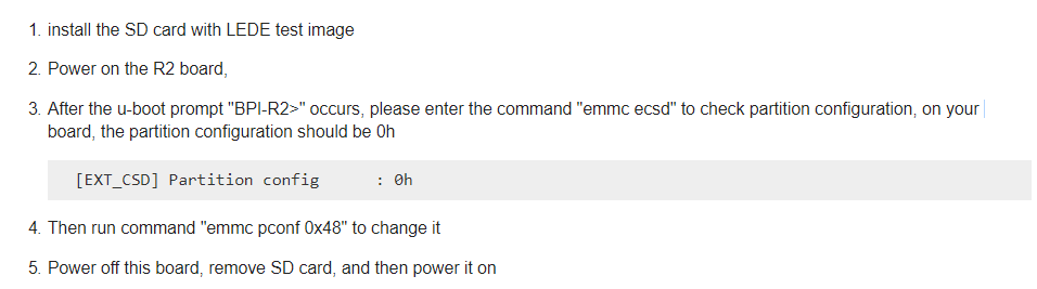
Please follow below steps to change a setting for EMMC, and then the lede image will work fine.
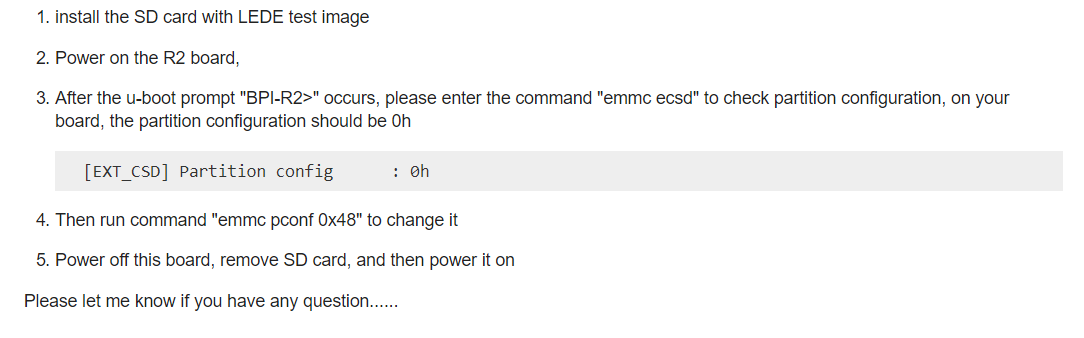
Sorry. Everything works. I made mistake to connect serial ttl to GPIO uart instead of u-boot uart debug.
Thank you gary a lot. This did the trick! Now I boot to LEDE from SD card and EMMC as well. I believe it would be useful to add this hint here: https://bananapi.gitbooks.io/banana-pi-bpi-r2-open-source-smart-router/content/openwrt.html.
So partial success so far. Unfortunately I still do not boot the Ubuntu. I moved my ask for help here (believe it is the better thread for that topic than this one):
@garywang could you please compile test images every let’s say week? (I beleve someone make progress in development …)
Do I need to fat SD before carry on step 2?
I move SD card to my R2 board and then power on it, but get nothing output from debug UART.
No need to format the SD, please follow below steps to change the EMMC setting.
Hello Gary I have the same issue. Please, how can we manage to still boot from Emmc and keep custom settings over any reboot ? What is the alternative ? Keeping LEDE booting on SD Card ?
The squashfs and jffs2 are working fine, please check above comment for details.
I just copied the image onto the sd card, and when I try to boot the banana pi R2 I just get this kind of violet screen with no prompt/console or anything like that, can you help me out?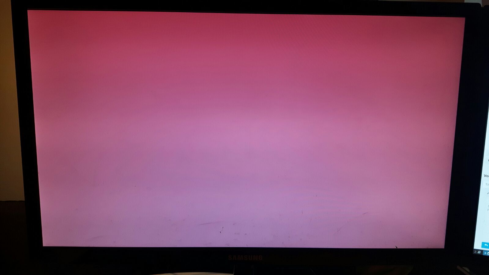
(Same issue like @pkalemba @Tohin @Maciek_Szelagowski)
To Have console you need to ssh or Have a uart serial cable, as i said in post above Lede does not Have graphical interface