BPI M1+ UART3 (TTYS2) not Working

I have BPI M1+ …

I am trying to use the UART on GPIO pins 8 & 10 (similar to raspberry pi) from what i understand this should be device ttyS2.

However it does not seem to work no matter what i try, I am using the latest BPI jessie distribution (15.08) from here :-

https://www.bananian.org/download

Output from console during boot shows 4 UART’s found …

[ 0.621277] Serial: 8250/16550 driver, 32 ports, IRQ sharing disabled [ 0.629673] [uart]: used uart info.: 0x95 [ 0.634395] [uart]: serial probe 0 irq 33 mapbase 0x01c28000 [ 0.660771] sunxi-uart.0: ttyS0 at MMIO 0x1c28000 (irq = 33) is a U6_16550A [ 0.665708] [uart]: serial probe 2 irq 35 mapbase 0x01c28800 [ 0.691946] sunxi-uart.2: ttyS1 at MMIO 0x1c28800 (irq = 35) is a U6_16550A [ 0.696827] [uart]: serial probe 4 irq 49 mapbase 0x01c29000 [ 0.723041] sunxi-uart.4: ttyS2 at MMIO 0x1c29000 (irq = 49) is a U6_16550A [ 0.727925] [uart]: serial probe 7 irq 52 mapbase 0x01c29c00 [ 0.754137] sunxi-uart.7: ttyS3 at MMIO 0x1c29c00 (irq = 52) is a U6_16550A

I have a read a few posts from other users suggesting that that they to have a similar issue but no solutions so far …

Any advice or help on how to get it working ?

Cheers Jay

Check Armbian and follow this how to:

http://forum.armbian.com/index.php/topic/371-cubietruck-uart-3-4-7-pin-out-serial-ttys/

It’s for Cubietruck which mean you only need to check the PIN numbers.

1 Like

Thanks for the link … will read up on it …

Cheers Jay

@igorpec,

I’ve read the post you linked to above and the subsequent links within that post and i think i understand what needs to be done and the processes involved.

I have downloaded the latest BPI kernel source files and they compile ok.

However i am unable to find the correct dts file for sunti-a20… nor do i understand where the compiled dtb file should be placed once the changes are made.

the dts folder in the kernel source does not seem to have a sunxi/BPI dts file ?

The the only dts file i can find that seem applicable is this one …

https://github.com/torvalds/linux/blob/master/arch/arm/boot/dts/sun7i-a20-bananapi.dts

But its not in the source and i’m not sure if it is for M1+, can some one please confirm the correct dts file for Banana Pi M1+

Have searched for a guide on editing dts files and compiling them into dtb files but it seems to be a subject that is not common … I’ve never had to work with dts files so its all new to me.

If anyone knows of a good guide please post a link …

I don’t understand why the extra uarts are not enabled by default as they are declared in the M1+ fex file which seems to assign the correct pins (PH04 & PH05 for the uart on pins 8 + 10 on con 3)… The board is marketed with the extra serial ports so it seems odd that they can not be used out of the box ?

Any additional help greatly appreciated

Cheers Jay

Most likely this doesn’t exist :smile:

The SinoVoip people don’t give a sh*t about their hardware being supported by mainline kernel but follow a rather moronic ‘development approach’ (in fact they do not develop anything but instead clone other github repos and hide the only files of interest somewhere inside).

You have to crawl through any of the SinoVoip repos here https://github.com/BPI-SINOVOIP?tab=repositories to search for ‘kernel 4’ or ‘mainline’ or something like that and therein for the M1+ stuff. But since they usually just do copy&paste from somewhere else you’ll end up with a .dts for LeMaker’s Banana Pro that’s not correct in every regard.

And you should be aware that since SinoVoip doesn’t follow any ‘open source’ standards when developing software (they think it’s enough to release something way too late on github to behave like ‘open source community members’) you have to crawl through any of their countless/useless github repos as well as the official ones upstream.

Have a look at this example with the M2. The SinoVoip folks did copy&paste from somewhere else and created a slightly working .dts file for the M2 a few months after the device has been available to the public. Then one member of the linux-sunxi community corrected their mistakes by writing a new device tree file from scratch and what they do? Post a useless thread in this forum but do NOT exchange their crappy .dts file with the good one from mainline kernel in their OS image or their useless github repos: Uboot have official support BPI-M2

BTW: We’re always talking about mainline kernel here. If you’re relying on kernel 3.4 then the whole procedure is completely different (no .dts but fex file instead).

1 Like

Many thanks for the (slightly worrying) info … i moved to BPI to use for a OpenHAB project, i chose M1+ as it has SATA and 4 Uarts … i’m starting to find that detailed/low level info on M1+ is hard to find with limited manufacture support … which is a real shame as M1+ seems like a good hardware base with all the extra features such as wifi & sata (both of which i have working)

cant belive that they dont have an image that enables the use of the extra uarts … madness

Am beginning to think if i should look for another sbc that has better support ?

Still your last post does explain the missing files as i am using their latest jessie build

# uname -a Linux PLS-HUB 3.4.108-bananian #2 SMP PREEMPT Thu Aug 13 06:08:25 UTC 2015 armv7l GNU/Linux

I found the fex files on the boot loader partition and there is a separate folder for each BPI veriant including M1+.

The script.fex file for the M1+ does seem to define uart4 to use pins PH04 & PH05 which i think is correct for con 3 pin 8 (TX) & pin 10 (RX) which are the same physical GPIO pins as on Rasp Pi.

section of M1+ script.fex

[uart_para4] uart_used = 1 uart_port = 4 uart_type = 2 uart_tx = port:PH04<4><1> uart_rx = port:PH05<4><1>

So would this suggest that the uart on con 3 pins 8+10 is ttyS4 and not ttyS2 as in the documentation ?

Cheers Jay

The count of available UARTS depends on the SoC being used and whether the pins are available to the outside. I don’t know how to tell since the picture above has nothing to do with ‘specifications’ – it’s just a photoshopped image they took from raspberrypi-spy.co.uk (they use the same for the M2 and probably for the M3 too – since who cares whether the GPIO pin mapping is correct or not?):

http://www.bananapi.com/index.php/forum/general-discussion-for-bpi-m2/411-m2-gpio-defininiton?start=6

You might want to check the schematics (assumed they are correct) to get a clue which pins are available where. You might have to crawl through this and also the old forum (since SinoVoip people love it to post links to google drive containing essential informations somewhere inside a thread here and there) and any github ressources they publish.

Just realized that I added this info to the Banana Pi’s information page: http://linux-sunxi.org/Banana_Pi#See_also (in case you want to have any informations about Banana Pi related stuff better have a look in the linux-sunxi wiki since the people responsible there care about correctness)

In case you don’t know or let’s better say not already stumbled across: http://linux-sunxi.org/Fex_Guide#uart_configuration

And after altering the contents and replacing script.bin the following two commands might be useful after the following reboot:

dmesg | egrep "serial|uart"
sudo cat /proc/tty/driver/serial

@tkaiser,

I knew about that 1st link which i’ve been using as a reference for the correct uart def syntax …

and i posted the output of dmesg | egrep “serial|uart” in my 1st post …

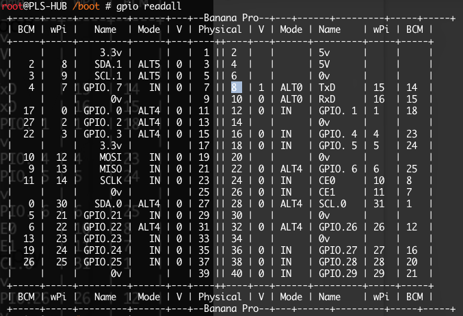
The output would suggest that the four on board uarts are bound to ttySx devices ? so it should work unless the pin allocations in the M1+ fex file is wrong ?

i can use

stty -F /dev/ttySx 9600 ( where x = 0-3)

to set baud rate on each uart port and stty returns without any errors … if i do the same for ttyS4 - ttyS9

1 root@PLS-HUB ~ # stty -F /dev/ttyS4 9600
stty: /dev/ttyS4: Input/output error

returns I/O error, even though ttyS4 - ttyS9 exists as virtual device in /dev

1 root@PLS-HUB ~ # ls /dev/tty

/dev/tty /dev/tty18 /dev/tty28 /dev/tty38 /dev/tty48 /dev/tty58 /dev/ttyS1 /dev/ttyS2 /dev/ttyS3 /dev/tty0 /dev/tty19 /dev/tty29 /dev/tty39 /dev/tty49 /dev/tty59 /dev/ttyS10 /dev/ttyS20 /dev/ttyS30 /dev/tty1 /dev/tty2 /dev/tty3 /dev/tty4 /dev/tty5 /dev/tty6 /dev/ttyS11 /dev/ttyS21 /dev/ttyS31 /dev/tty10 /dev/tty20 /dev/tty30 /dev/tty40 /dev/tty50 /dev/tty60 /dev/ttyS12 /dev/ttyS22 /dev/ttyS4 /dev/tty11 /dev/tty21 /dev/tty31 /dev/tty41 /dev/tty51 /dev/tty61 /dev/ttyS13 /dev/ttyS23 /dev/ttyS5 /dev/tty12 /dev/tty22 /dev/tty32 /dev/tty42 /dev/tty52 /dev/tty62 /dev/ttyS14 /dev/ttyS24 /dev/ttyS6 /dev/tty13 /dev/tty23 /dev/tty33 /dev/tty43 /dev/tty53 /dev/tty63 /dev/ttyS15 /dev/ttyS25 /dev/ttyS7 /dev/tty14 /dev/tty24 /dev/tty34 /dev/tty44 /dev/tty54 /dev/tty7 /dev/ttyS16 /dev/ttyS26 /dev/ttyS8 /dev/tty15 /dev/tty25 /dev/tty35 /dev/tty45 /dev/tty55 /dev/tty8 /dev/ttyS17 /dev/ttyS27 /dev/ttyS9 /dev/tty16 /dev/tty26 /dev/tty36 /dev/tty46 /dev/tty56 /dev/tty9 /dev/ttyS18 /dev/ttyS28 /dev/tty17 /dev/tty27 /dev/tty37 /dev/tty47 /dev/tty57 /dev/ttyS0 /dev/ttyS19 /dev/ttyS29 root@PLS-HUB ~ #

So i would have thought that this would suggest that all four hardware uarts are accessible ?

but

echo “This is a test” > /dev/ttyS2

Results in nothing being transmitted ? same goes if i use mini com and send data from Arduino … nothing received ?

output of the other command you suggested

1 root@PLS-HUB ~ # cat /proc/tty/driver/serial

serinfo:1.0 driver revision: 0: uart:U6_16550A mmio:0x01C28000 irq:33 tx:0 rx:0 1: uart:U6_16550A mmio:0x01C28800 irq:35 tx:0 rx:0 2: uart:U6_16550A mmio:0x01C29000 irq:49 tx:12 rx:0 3: uart:U6_16550A mmio:0x01C29C00 irq:52 tx:0 rx:0 4: uart:unknown port:00000000 irq:0 5: uart:unknown port:00000000 irq:0 6: uart:unknown port:00000000 irq:0 7: uart:unknown port:00000000 irq:0 8: uart:unknown port:00000000 irq:0 9: uart:unknown port:00000000 irq:0 10: uart:unknown port:00000000 irq:0 11: uart:unknown port:00000000 irq:0 12: uart:unknown port:00000000 irq:0 13: uart:unknown port:00000000 irq:0 14: uart:unknown port:00000000 irq:0 15: uart:unknown port:00000000 irq:0 16: uart:unknown port:00000000 irq:0 17: uart:unknown port:00000000 irq:0 18: uart:unknown port:00000000 irq:0 19: uart:unknown port:00000000 irq:0 20: uart:unknown port:00000000 irq:0 21: uart:unknown port:00000000 irq:0 22: uart:unknown port:00000000 irq:0 23: uart:unknown port:00000000 irq:0 24: uart:unknown port:00000000 irq:0 25: uart:unknown port:00000000 irq:0 26: uart:unknown port:00000000 irq:0 27: uart:unknown port:00000000 irq:0 28: uart:unknown port:00000000 irq:0 29: uart:unknown port:00000000 irq:0 30: uart:unknown port:00000000 irq:0 31: uart:unknown port:00000000 irq:0 root@PLS-HUB ~ #

Again this would suggest that all four uarts are assigned to devices ?

Completely confused as to what the issue could be ?

Cheers Jay

Right … have trawled through the forums that you mentioned and have found out the following

According to [schematics][1] the uart on con 3 pins 8 + 10 is uart3

According to [A20 IO Map][2] uart 3 pin outs are on port bank ‘H’

uart3 TX = PH00 (MUX 4) uart3 RX = PH01 (MUX 4)

the default fex file for M1+ (uart3 section)

[uart_para3] uart_used = 0 uart_port = 3 uart_type = 2 uart_tx = port:PH00<4><1> uart_rx = port:PH01<4><1>

the ports and mux seem to be correct so the solution should be to change ‘uart_used = 1’ recompile fex file using fex2bin and copy new script.bin to root of bootloader folder on sd card.

So i’ve done all that and now on bootup uart3 is detected and assigned to ttyS2 which matches what some documentation says it should be … really don’t understand why its not already enabled in the defaut fex file but hey this is progress.

root@PLS-HUB / # dmesg | egrep “serial|uart”

[ 0.629693] [uart]: used uart info.: 0x9d [ 0.634421] [uart]: serial probe 0 irq 33 mapbase 0x01c28000 [ 0.660769] sunxi-uart.0: ttyS0 at MMIO 0x1c28000 (irq = 33) is a U6_16550A [ 0.665707] [uart]: serial probe 2 irq 35 mapbase 0x01c28800 [ 0.691939] sunxi-uart.2: ttyS1 at MMIO 0x1c28800 (irq = 35) is a U6_16550A [ 0.696826] [uart]: serial probe 3 irq 36 mapbase 0x01c28c00 [ 0.723031] sunxi-uart.3: ttyS2 at MMIO 0x1c28c00 (irq = 36) is a U6_16550A [ 0.727900] [uart]: serial probe 4 irq 49 mapbase 0x01c29000 [ 0.754093] sunxi-uart.4: ttyS3 at MMIO 0x1c29000 (irq = 49) is a U6_16550A [ 0.758957] [uart]: serial probe 7 irq 52 mapbase 0x01c29c00 [ 0.785154] sunxi-uart.7: ttyS4 at MMIO 0x1c29c00 (irq = 52) is a U6_16550A root@PLS-HUB / #

but setting baud rate with stty and sending test data still doesn’t work.

But now i’m wondering if the 3.3 volts which i’m taking from the 40 pin gpio header is up to driving the 3.3v to 5V logic converters necessary for interfacing to Arduino uart… worked fine on rasp pi but i’ve now read that 3.3v on BPI gpio is extremely low current ?

Gosh … I’ve never had such convoluted info and uart problems with any other SBC’s …

Everyday a School Day with linux …

Cheers Jay [1]: https://drive.google.com/file/d/0B4PAo2nW2KfnNTk5WnVSV0lPejA/view [2]: http://linux-sunxi.org/A20/PIO

After enabling Uart 3 (see post above) i’m pretty sure the fex and pin configs are correct for uart 3 and that its been assigned to ttyS2.

But i still cant get it to work, even performing a simple loop back test using minicom by connecting Tx to RX does not work so i don’t think it can be anything to do with logic level conversion, i seems that the BPI is still not using the uart correctly ?

Has anybody out there successfully used the uart on con 3, pins 8 + 10 (PH00,PH01) ???, i am beginning to wonder if Banana Pi Pro/M1/M1+ has a manufacturing defect that prevents the use of uart3 successfully which is why its been disabled in the default fex file ?

I installed the BPI build of the gpio utility and performing a ‘readall’ outputs the following

Can anybody confirm if ALT0 is the correct mode for pins 8 + 10 to work in uart mode ?

Any comments much appreciated …

Cheers Jay

http://forum.lemaker.org/thread-2937-1-1.html

There was the ‘official’ forum before the ‘official’ forum became the one at bananapi.com (that is now abandoned because the next weeks/months this here will be the ‘official’ forum where you don’t get any support by the vendor). Back at that time there were people being paid for supporting the Banana Pi.

@tkaiser,

I’m a bit confused by your description of the history forums … I think what you are saying is that this is now/soon to be the correct forum for BPI M1+ but there is no official support for it so everyone use the other forum ?

if so then thats a bit crap isn’t it ?

I already found that post you linked but its of no help … that post seems to be related to 1st gen BPI with 26 pin GPIO header and separate headers for the other uarts …BPI PRo/M1+ has all in one 40 pin gpio header … however what is outlined in that post is basically what i’ve done but it still does not work … so can only conclude that there is some sort of design fault hence the reason its disabled by default in fex file ?

Comparing gpio readall to rpi B+ (with uart3 woking) indicates that ALT0 is correct so completely at a loss now …

This is getting to the point where its not worth the effort I must have spent at least 20 hours trying to get uart3 to work on BPI M1+ GPIO … might just be simpler to chuck it in the bin and get something that works or at least has official support and documentation.

Very disappointed now with M1+

Jay

Have a look at http://linux-sunxi.org/Banana_Pi#Variants (and also on the top of that page that might clarify the situation why there was more than one company claiming it’s the Banana vendor). SinoVoip tried to copy LeMaker’s BananaPro exactly so that software should be interchangeable 1:1 – but they failed regarding audio_pa_ctrl and maybe other things are also routed differently – we will never know since SinoVoip doesn’t answer support questions).

Now that LeMaker had to give up on supporting the Bananas it’s a product without support at all :frowning:

That’s a bit sad because I like the M1+ more than the Pro since it has all the stuff that might get hot (SoC and PMU) on the upper PCB side so that enclosures don’t lead to thermal issues under full load as it’s the case with Banana Pi M1 and Pro.

@tkaiser,

Many thanks for your posts and explanations, had i known that BPI M1+ has such poor official support i would have thought twice about going this route. As you say its a shame as the hardware is mostly very good and it is running all of our software extremely well from a ssd via sata2 interface and communicating with mobile devices via built in wifi (configured as AP) all of this works much better and faster than Rasp PI.

I didn’t realise that M1+ is a clone of a clone and the mixed manufacturing vendors and poor history of Banana Pi with regards to official vendor support, i guess you only find out about these issues when you run into problems and start reading the small print …

I think you maybe correct about the problem with the audio_pa_ctrl not not being the only diffrance with regards to pin changes between the A20 and the external interfaces … so for me it time to call it quits with Banana Pi M1+

Unless someone can chime in and tell me categorically that uart3 (ttyS2) does work on M1+ gpio and what needs to be done to make it work i can not spend any more time on this. For now we will have to go back to Raspberry Pi … it maybe slow but it does work.

We may revisit it in the future … it should be possible to use the debug uart ttyS0 on con4 (assuming that works) to communicate with our daughter board but we will need to make a new hardware revision of our DB as currently all I/O is via gpio connector.

Thanks for getting me this far.

Cheers Jay

justin have to test it ,and will let you know result later . sorry for delay.

I would wait and let Justin test and confirm. If you got that far (official answer from SinoVoip) it’s too early to give up! :smile:

Apart from that I would believe https://www.olimex.com is worth a look. Their OLinuXinos come with 160 GPIO pins and I believe they route everything to the outside that’s possible. And since they follow the ‘open source hardware’ rules you find there excellent documentation ‘by design’.

Thank you, i hope you can help as this is a very frustrating situation as everything else is working on M1+, please be sure to read this entire thread from post #10 onwards as i have tried very hard to get uart3 working and believe that i have done everything correct,

Fingers crossed that SinoVoip can find the answer …

Cheers Jay

The dts file for bpi-m1-plus is here https://github.com/BPI-SINOVOIP/BPI-Mainline-uboot/tree/master/arch/arm/dts

The diff against mainline uboot is here. http://users.utu.fi/jmjmak/tmp/uboot-bananapi.patch

This 4.2 kernel also works, but it’s quite bloated with extra config:

As stated in post #6 onwards I am using the BPI Debian/Jessie 15.08 release which uses u-boot so fex files are used for pin config not DTS … We just cant afford to spend any more time trying to get uart3 working right now …

However since my last post we have had very good success using uart7 (GPIO pins 36 & 38) as an alternative which has allowed us to progress with testing BPI M1+ … unfortunately it also meant we have had to create a prototype BPI M1+ specific version of our daughter board with a 40 pin connector which will not be backwards compatible with Rasp Pi which was our original intention.

However having seen the performance gains between BPI M1+ against Rasp Pi Model B this may not be so much of an issue now

For now please consider this thread closed, but we would always be interested if anyone is eventually successful in getting uart3 working in the future …

Cheers Jay