Banana Pi BPI-M4 : Question about the Device Tree. The target WiFi module requires SDIO Pull Up

Hi All

My wifi module connects with the sdio interface.(LILY-W1) It doesn’t use the built-in WiFi to use the certified module.

This module requires SDIO PullUp, but in the DTC file it looks like PullDown. (Please check if this recognition is acceptable.) The relevant parts of the DTC file are as follows.

        sdcard_low {
                linux,phandle = <0x26>;
                phandle = <0x26>;
                realtek,function = "mmc";
                realtek,pins = "gpio_39\0gpio_38\0gpio_37\0gpio_36\0gpio_33\0gpio_32";
                realtek,pull_en = <0x01>;
                realtek,pull_sel = <0x00>;
        };

dmesg is below.

On the other hand, according to the LILY-W1 manual, a 50KΩ Pull Up is required. Is this difficult with PullUp built into the device? Should I solder it to the outside?

[ 1235.386941] rtk_sdmmc_int_wait: reset the card and adjust the driving capacity, cmd=1, SD_TRANSFER=0x78
[ 1235.397026] rtk-sdmmc 98000000.sdmmc: card claims to support voltages below defined range
[ 1235.400122] mmc0: error -3 whilst initialising MMC card
[ 1235.688437] rtk_sdmmc_get_cd: SD card exists, card_exist = 0x32bf04
[ 1235.698454] rtk_sdmmc_get_cd: SD card is being inserted now...!!!
[ 1235.879197] rtk_sdmmc_timeout: command/data timeout, pre_cmd=0, cmd=8, poll=0, ISR=0, ISR_EN=6
[ 1235.879233] Reject SD 2.x command
[ 1235.879450] rtk_sdmmc_int_wait(1682) trans error(timeout) :
                trans: 0x00000008, st1: 0x00000000, st2: 0x00000000, bus: 0x0000001f
[ 1235.879462] rtk_sdmmc_int_wait: error opcode = 8
[ 1235.879887] Reject SD 1.x command
[ 1235.880292] Reject SD 1.x command
[ 1235.880698] Reject SD 1.x command
[ 1235.881100] Reject SD 1.x command
[ 1235.881514] rtk_sdmmc_int_wait: reset the card and adjust the driving capacity, cmd=1, SD_TRANSFER=0x78
[ 1235.891602] rtk-sdmmc 98000000.sdmmc: card claims to support voltages below defined range
[ 1235.894686] mmc0: error -3 whilst initialising MMC card
[ 1236.023136] SD card is being removed now...!!!
[ 1236.176478] rtk_sdmmc_get_cd: SD card does not exist, card_exist = 0x32bf0c

Please tell me the procedure to pull up. The target board is booted with emmc.

sdcard_low node is for sd, sdio_pins_1 node is for sdio, please check linux-rtk/arch/arm64/boot/dts/realtek/rtd1395/rtd139x.dtsi.

internal pullup

realtek,pull_en = <1>;
realtek,pull_sel = <1>;

internal pulldown

realtek,pull_en = <1>;
realtek,pull_sel = <0>;

bias disable

realtek,pull_en = <0>;
realtek,pull_sel = <0>;

Thanks.

I’m thinking of using the signal from the TF card, so I think sdio_pins_0 will be the target. It means the change as follows.

        sdio_pins_0 {
                realtek,function = "sdio_loc0";
                realtek,pins = "gpio_32\0gpio_33\0gpio_36\0gpio_37\0gpio_38\0gpio_39\0sdio_loc";
        };

    sdio_pins_0 {
            realtek,function = "sdio_loc0";
            realtek,pins = "gpio_32\0gpio_33\0gpio_36\0gpio_37\0gpio_38\0gpio_39\0sdio_loc";
                    realtek,pull_en = <1>;
                    realtek,pull_sel = <1>;
    };

image

I seem this fix to rtd-1395-bananapi-m4-1GB.dtb to next step. I’ll try it.

Unfortunately, I tried it, but the result was the same.

# dtc --sort -I fs -O dts  /sys/firmware/devicetree/base

                sdio_pins_0 {
                        realtek,function = "sdio_loc0";
                        realtek,pins = "gpio_32\0gpio_33\0gpio_36\0gpio_37\0gpio_38\0gpio_39\0sdio_loc";
                        realtek,pull_en = <0x01>;
                        realtek,pull_sel = <0x01>;
                };

root@bpi-iot-ros-ai:~/dtc# dmesg | tail -10
[  140.858271] rtk_sdmmc_int_wait(1682) trans error(timeout) :
                trans: 0x00000008, st1: 0x00000000, st2: 0x00000000, bus: 0x0000001f
[  140.858280] rtk_sdmmc_int_wait: error opcode = 8
[  140.859846] Reject SD 1.x command
[  140.860261] Reject SD 1.x command
[  140.860665] Reject SD 1.x command
[  140.861068] Reject SD 1.x command
[  140.861484] rtk_sdmmc_int_wait: reset the card and adjust the driving capacity, cmd=1, SD_TRANSFER=0x78
[  140.871575] rtk-sdmmc 98000000.sdmmc: card claims to support voltages below defined range
[  140.874687] mmc0: error -3 whilst initialising MMC card

sd and sdio have different driver and different dts configuration, not just repalce the gpios, sdmmc is for sd, please check the driver and dts first, enable sdio node, change gpios group and disable sd node.

I’m trying to connect a module to SD_D0/D1/D2/D3/CLK/CD (GPIO32-39). Because I have such a socket.

What you are saying is that it is wrong.

Does it mean that you need to connect to SDIO’s SDIO_D0/D1/D2/D3/CLK/CMD (GPIO40-45)?

If it is that , I will give up because it cannot be used for my evaluation.

Thanks.

Hiroaki

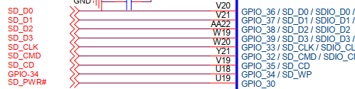
It seems that GPIO32-39 can be set to SDIO, so I modified the dts file. However, it stops in the middle of boot. I think my fix is wrong. I don’t have a data sheet so I don’t know any more. Would you please fix it correctly?

Thanks

sdio0@98010400 { /* sdmmc -> sdio0  Dekinaiiiiii */
        compatible = "Realtek,rtk1295-sdio";
        gpios = <0x1c 0x1e 0x01 0x00 0x1c 0x22 0x00 0x01 0x1c 0x23 0x00 0x01>;
/*                reg = <0x98010c00 0x200 0x98000000 0x200000>;  */
        reg =   <0x98000000 0x400>, /* CRT */
                <0x98010400 0x40>,  /* SDIO0 */
                <0x9801A000 0x400>, /* BS2 */
                <0x9804E000 0x40>,  /* ISO */
                <0x98010A00 0x40>,  /* SDIO */
                <0x98007000 0x200>;
        interrupts = <0x00 0x2c 0x04>;
        pinctrl-names = "default";
        pinctrl-0 = <0x26>;
        clocks = <0x1d 0x19 0x1d 0x1f>;
        clock-names = "cr\0sd_ip";
        resets = <0x21 0x0a>;
        status = "okay";
};
/*
sdmmc@98010400 {
        compatible = "Realtek,rtk1295-sdmmc";
        gpios = <0x1c 0x1e 0x01 0x00 0x1c 0x22 0x00 0x01 0x1c 0x23 0x00 0x01>;
        reg = <0x98000000 0x400 0x98010400 0x200 0x9801a000 0x400 0x9804e000 0x40 0x98010a00 0x40 0x98007000 0x200>;
        interrupts = <0x00 0x2c 0x04>;
        pinctrl-names = "default";
        pinctrl-0 = <0x26>;
        clocks = <0x1d 0x19 0x1d 0x1f>;
        clock-names = "cr\0sd_ip";
        resets = <0x21 0x0a>;
        status = "okay";
};
*/

I know you plug a socket wifi module to sd slot, but one pinctrl can’t be used for both sdmmc and sdio at same time, so you must disable sdmmc node, or change the pinctrl of sdmmc to another group.

I’ll ask you a little more politely.

I tried to define sdio at the address of sdio@98010400. After all it seems that the definition of the register is insufficient. Boot is possible, but SDIO is not detected.

/*
        sdio@98010A00 {
                compatible = "Realtek,rtk1295-sdio";
                gpios = <0x1c 0x1b 0x01 0x01>;
                reg = <0x98010c00 0x200 0x98000000 0x200000>;
                interrupts = <0x00 0x2d 0x04>;
                pinctrl-names = "default";
                pinctrl-0 = <0x25>;
                clocks = <0x1d 0x1e 0x1d 0x1a>;
                clock-names = "sdio\0sdio_ip";
                resets = <0x21 0x0c>;
                status = "disabled";
        };
*/

        sdio@98010A00 {
                compatible = "Realtek,rtk1295-sdio";
                gpios = <0x1c 0x1e 0x01 0x00 0x1c 0x22 0x00 0x01 0x1c 0x23 0x00 0x01>;
                reg = <0x98010c00 0x200 0x98000000 0x200000>;
                interrupts = <0x00 0x2c 0x04>;
                pinctrl-names = "default";
                pinctrl-0 =  <0x26>;
                clocks = <0x1d 0x1e 0x1d 0x1a>;
                clock-names = "sdio\0sdio_ip";
                resets = <0x21 0x0c>;
                status = "disabled";
        };

/*
        sdmmc@98010400 {
                compatible = "Realtek,rtk1295-sdmmc";
                gpios = <0x1c 0x1e 0x01 0x00 0x1c 0x22 0x00 0x01 0x1c 0x23 0x00 0x01>;
                reg = <0x98000000 0x400 0x98010400 0x200 0x9801a000 0x400 0x9804e000 0x40 0x98010a00 0x40 0x98007000 0x200>;
                interrupts = <0x00 0x2c 0x04>;
                pinctrl-names = "default";
                pinctrl-0 = <0x26>;
                clocks = <0x1d 0x19 0x1d 0x1f>;
                clock-names = "cr\0sd_ip";
                resets = <0x21 0x0a>;
                status = "okay";
        };
*/

With the understanding so far, I tried the following, but it doesn’t work. Is there a recommended setting, I would like to try it. I look forward to working with you.

  1. It is necessary to set sdio_pins_0 to pull_up and adapt it to sdmmc.
  2. sdio_pins_0 is set to pull_up.
  3. The handle of sdio_pins_0 is assumed to be 0x40.
  4. 0x40 was adapted to sdmmc.
  5. GPIO_33 was deleted from sdio_pins_0 because pull up is not required for CLOCK.
  6. compatible = “Realtek, rtk1295-sdio”;
  7. I also changed some gpios.

root@bpi-iot-ros-ai:/mnt/bananapi/bpi-m4/linux# vi rtd-1395-bananapi-m4-1GB.dts

        sdio_pins_0 {
                realtek,pins = "gpio_32\0gpio_36\0gpio_37\0gpio_38\0gpio_39\0sdio_loc";
                realtek,function = "sdio_loc0";
                realtek,pull_en = <1>;
                realtek,pull_sel = <1>;
                linux,phandle = <0x40>;
                phandle = <0x40>;
        };


    sdmmc@98010400 {
            compatible = "Realtek,rtk1295-sdio";
            gpios = <0x1c 0x1e 0x01 0x01>;
            reg = <0x98000000 0x400 0x98010400 0x200 0x9801a000 0x400 0x9804e000 0x40 0x98010a00 0x40 0x98007000 0x200>;
            interrupts = <0x00 0x2c 0x04>;
            pinctrl-names = "default";
            pinctrl-0 = <0x40>;
            clocks = <0x1d 0x19 0x1d 0x1f>;
            clock-names = "cr\0sd_ip";
            resets = <0x21 0x0a>;
            status = "okay";
    };

You didn’t understand what i said, I think you should read the dts source file instead of decompile the dtb, and learn some dts basic knownledge before you do this work.

Please tell me.

Is the information in each configuration register unnecessary to describe the correct dts file? I am doing trial and error in the absence of that information. If you are an expert and you don’t need them and you can build a dts file with the information that is open now, I will study more and more. If it is necessary and it is close, it is useless to study, so consider other methods. Especially if you need to change the register settings for sdmmc and sdio